A couple of week’s ago, I wrote about the construction of the Greenwich foot tunnel, based on a pamphlet published in 1902 by the Institution of Civil Engineers. The pamphlet included details of another recent tunnelling project, constructing the tunnels of the Baker Street and Waterloo Railway (known from the start as the Bakerloo line), under the Thames between Embankment and Waterloo Stations.
Parliamentary Acts of 1893 and 1896 had approved construction of the Baker Street and Waterloo Electric Railway, initially running from Dorset Square near Marylebone Station, to Waterloo Station. Further requests for extensions were approved and by 1904 the line ran from Paddington to Elephant and Castle.
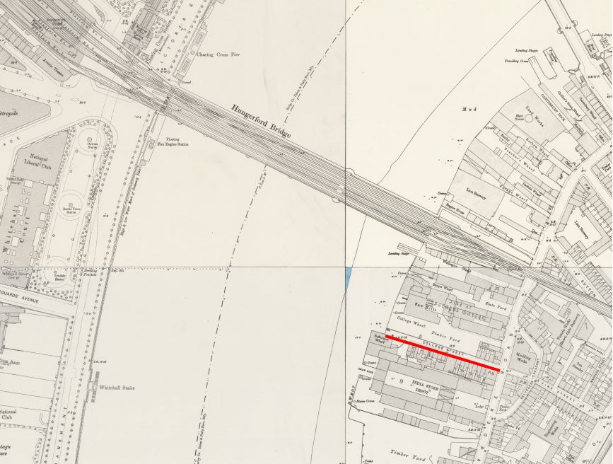
The route of the Baker Street and Waterloo railway ran beneath the Baker Street Station of the Metropolitan District Railway, by Regent’s Park and Crescent Gardens into Portland Place, through Langham Place to Oxford Circus (where the tunnels pass over those of the Central Line with a clearance of only 6 inches at one point), down Regent Street to Piccadilly Circus, along Haymarket and Cockspur Street to Charing Cross, along Northumberland Avenue, then under the Thames to College Street, Vine Street and Waterloo Station.
The majority of the tunnel went through London Clay and was a relatively easy construction project, however there was a challenge where the tunnel went underneath the Thames.
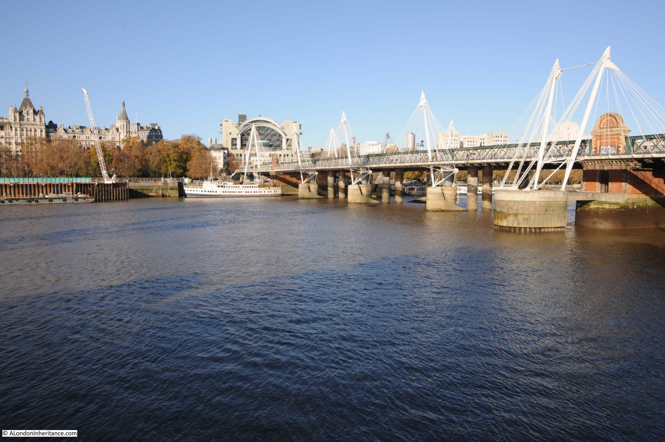
The following diagram from the pamphlet shows the route under the river, from Northumberland Avenue to College Street on the opposite side of the river. The station shown above Hungerford Bridge, labelled Charing Cross Station, is now Embankment Station.
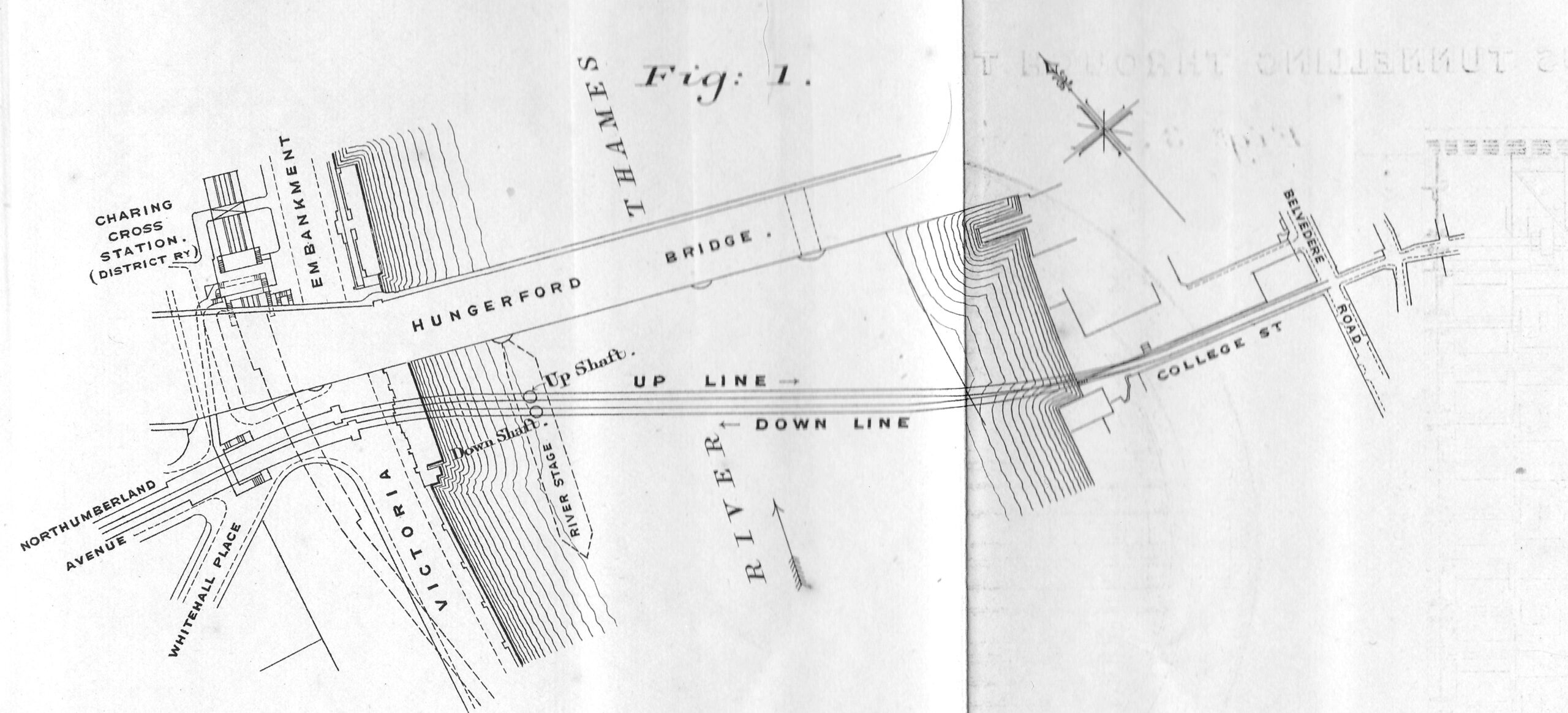
The diagram shows a “River Stage” extending south from Hungerford Bridge. This was a large platform, 50 feet wide and 370 feet long on which were built workshops, stores, steam cranes, boilers and air-compressors, staff buildings along with two shafts down to where the tunnels would be built.
The construction platform and shafts on the Thames were needed due to a strange anomaly found in the bed of the river when test boreholes were made along the route of the tunnels.
In the middle of the river there was a sudden depression in the London Clay through which the rest of the tunnel had been bored. This had filled with gravel, which was porous to water and required a different tunnelling method to the rest of the route, which would use compressed air to help keep out water as the tunnel went through the gravel.
The following diagram shows the route under the Thames of the Baker Street and Waterloo railway, the depression in the London Clay and short distance of gravel through which the tunnel would need to run.
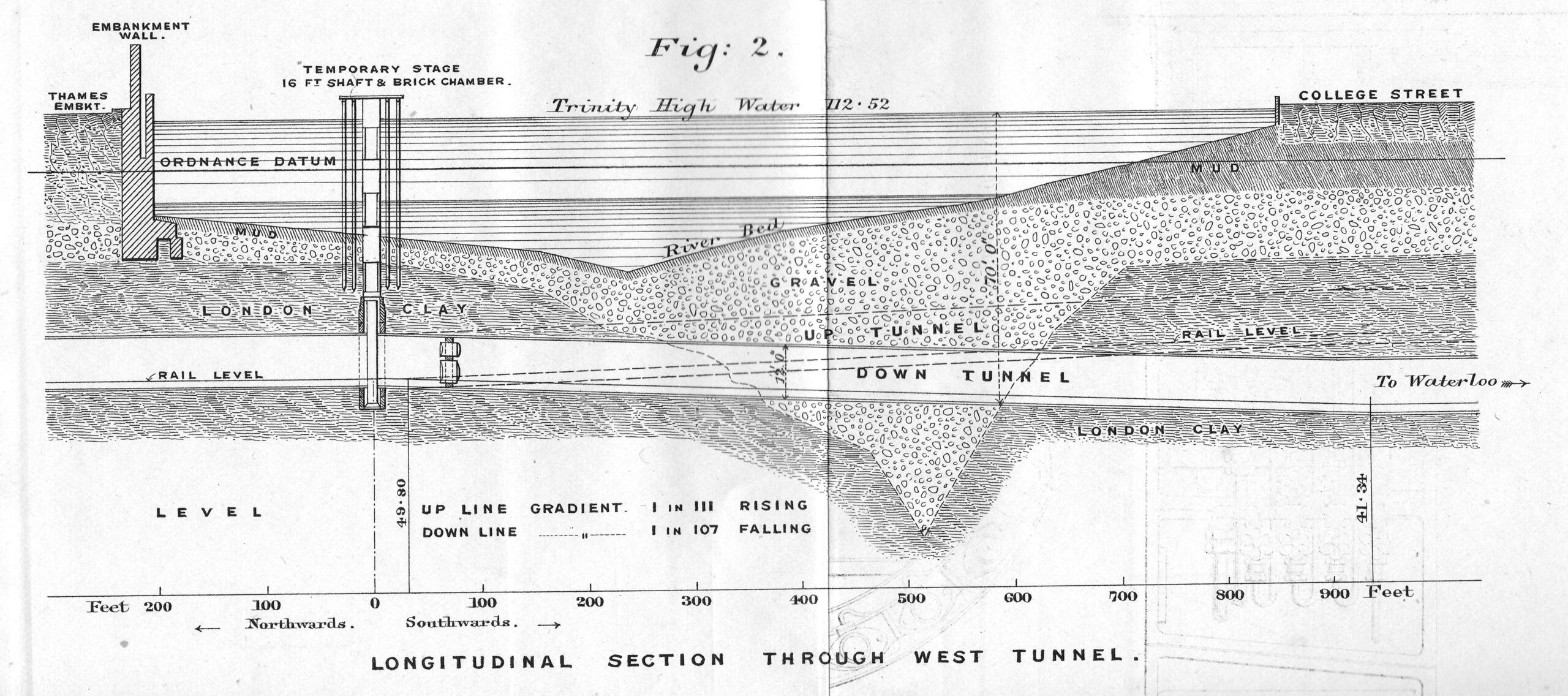
The diagram also shows the shafts sunk down to the level of the tunnels for their construction, along with the temporary work platform created on the river.
College Street on the right is now under the Jubilee Gardens.
Note also in the diagram how the depth of the two tunnels diverge as they route under the Thames, with the “up” line having a rising gradient towards Waterloo (shown as dotted lines) and the “down” tunnel having a descending gradient towards Waterloo.
The ground beneath the streets and buildings of London is generally invisible, but is just as interesting as the surface. I have written about some of the areas where the geology beneath the city has influenced the development of an area, for example, how water shaped north Clerkenwell, Bagnigge Wells, St. Chad’s Place and a Lost Well, and also when oil was found beneath the streets of Willesden.
There are many features below the surface, some as a result of ice and freezing, some as a result of water, for example when the Thames was a much wider river, and the multiple smaller rivers that ran into the Thames, and some the result of human activity.
I wondered whether the feature shown in the 1902 pamphlet was still there. I suspect we look at the Thames at low tide, and assume a uniform bed to the river as it descends from one side of the river, to rise on the opposite side.
The Port of London Authority (PLA) have a complete set of survey and navigation charts on their website, detailing the river from Teddington to Southend. They show a very different view of the Thames, a view that is essential to those on the river. The depth of water, obstructions, navigation lights, moorings etc.
A view where bridges almost disappear, with only the piers supporting the bridge shown on the chart, as these are the key features for those on the river.
The PLA kindly gave permission for me to include an extract from the chart for Lambeth Reach in today’s post, an extract which covers the area where the tunnel for the Baker Street and Waterloo Railway was constructed.
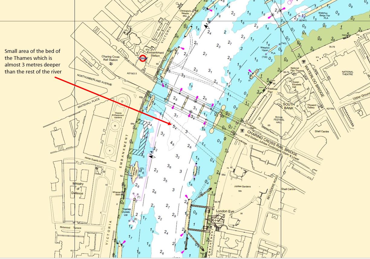
Hungerford Bridge can be seen in the centre of map, although only shown by black lines, with the piers supporting the bridge as the key feature.
The depth of the water is shown in metres (the depth is the average depth at the lower of each day’s two tides, which should show the minimum depth of water for those travelling along the river). The green areas along each side of the river are where the land is exposed at each low tide, with the height being shown (numbers underlined).
The depth of the Thames is typically between 2 and 3 metres at low tide in the central part of the river, however as can be seen just south of Hungerford Bridge (arrowed) there is a small area where the depth increases to a maximum of 5.4 metres, which is the same area as the depression in the London Clay shown in the 1902 diagram. Today’s Bakerloo line runs a short distance below the deepest area of this depression.
The PLA charts show how the depth of water gradually increases as the Thames heads towards the estuary, which is to be expected. They are some other similar features to the depression by Hungerford Bridge. For example, just off Limehouse Marina, there is a small area where the bed of the river suddenly descends from an average depth of between 6 and 7 metres, down to 11.7 metres, which is quite a depth at low tide.
Returning to the 1902 diagram of the route of the tunnels, it shows the tunnels running under College Street on the south bank of the river. This is one of the many streets that were lost following clearance of the area for the Festival of Britain.
The 1894 Ordnance Survey map shows the location of College Street (underlined in red) in the following extract (‘Reproduced with the permission of the National Library of Scotland“):
Interesting to compare the above map with the PLA chart. In the OS map, the priority is the land, so the river is shown as a blank stretch of water, with no defining features.
The location of College Street today, is under the northern edge of the Jubilee Gardens. The Thames has also been pushed back, with the construction of the embankment and walkway along the river for the Festival of Britain. In the following map, I have marked the location of College Street, pre-1950 edge of the river, where the shafts to the tunnels and the working platform were located, along with the route of the tunnels which today form the Bakerloo line ( © OpenStreetMap contributors).
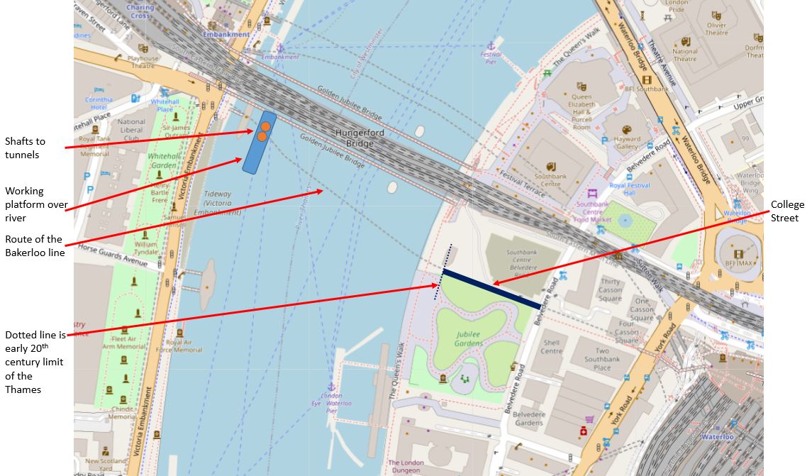
Looking at the area today, the tunnels of the Bakerloo line, run roughly under the blue van in the photo below. The edge of the grass to the right is the approximate pre-1950 boundary with the Thames.
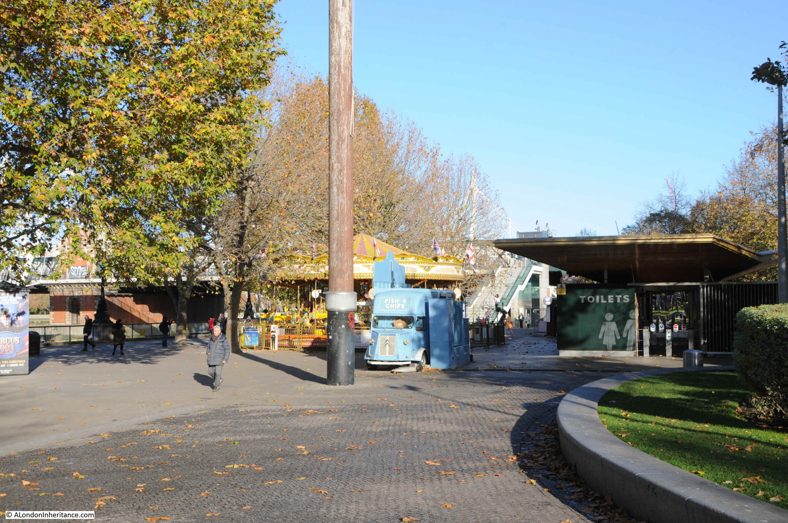
This view is looking back towards Waterloo Station from the walkway along the south bank, following the route of the Bakerloo line tunnels and College Street:
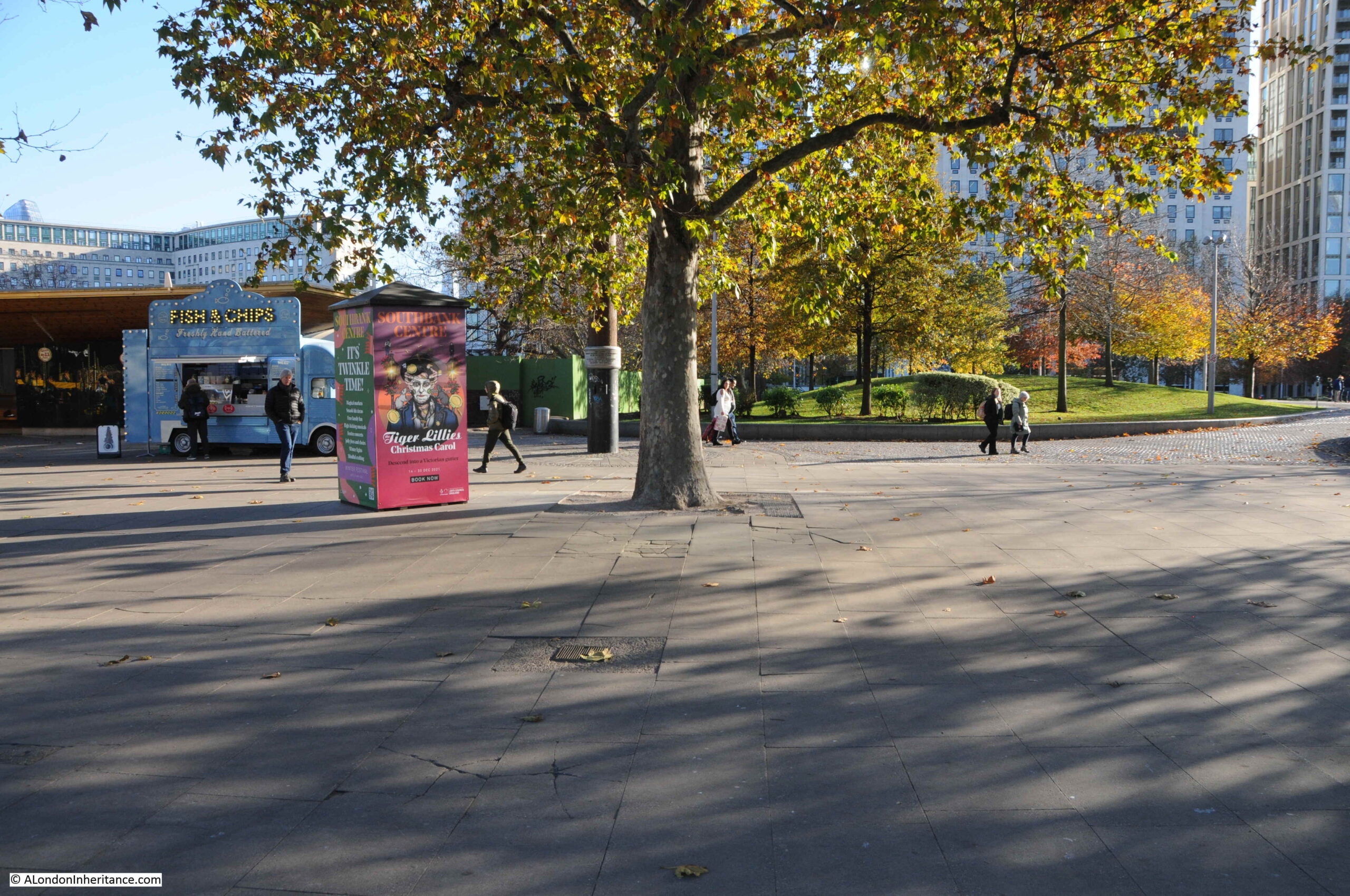
in the following view, the work platform extended from the first bridge pillars on the opposite side of the river (in front of the white boat) and extended 370 feet to the left. The depression in the London Clay is in the centre of the photo, and the Bakerloo line tunnels are running from the white ship to where I am standing to take the photo.
One of the benefits stated in the 1902 pamphlet of the work platform in the river was that material excavated during the construction of the tunnels could be taken away by barge, saving the transport of large amounts of material through the city’s streets.
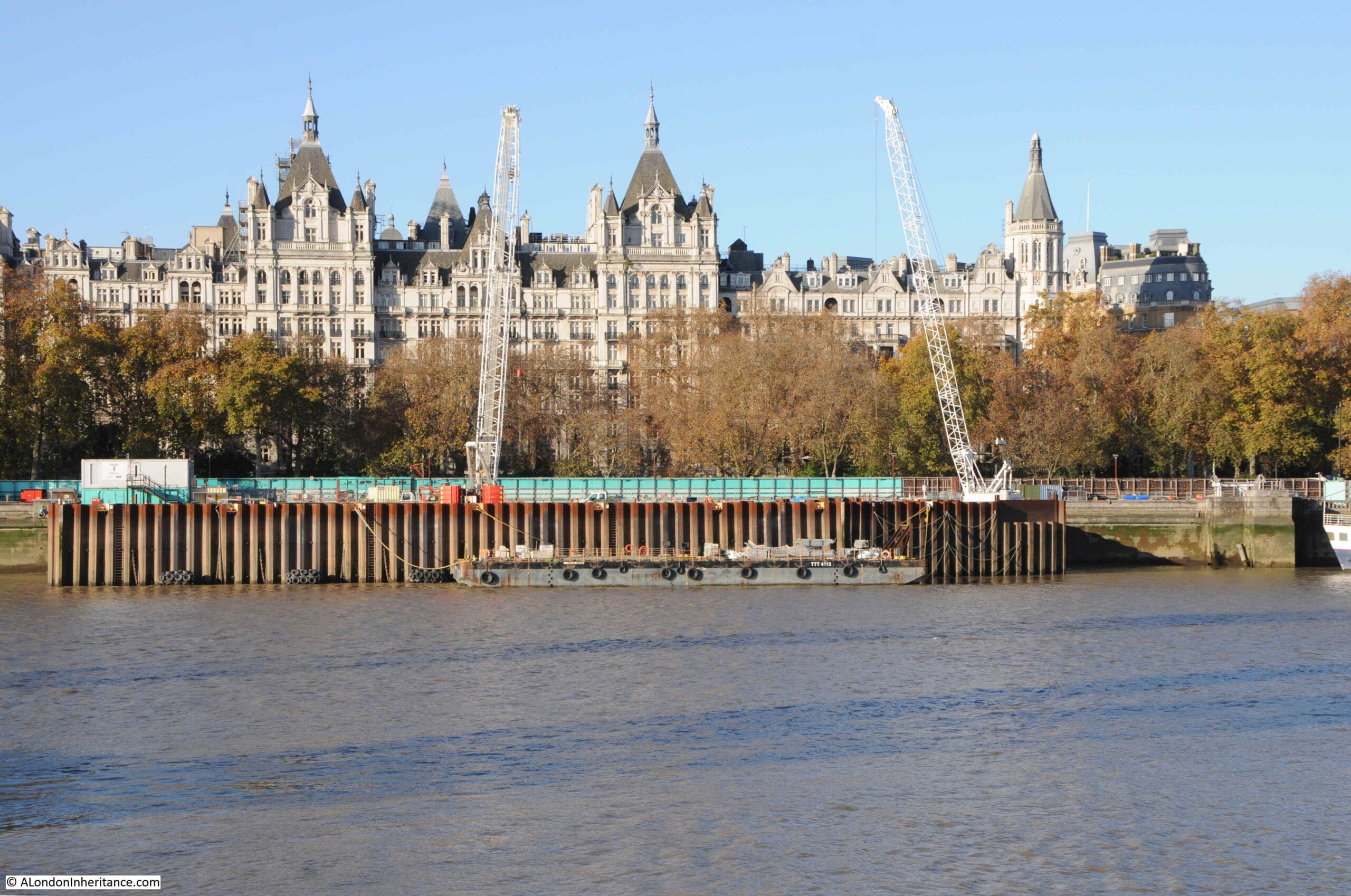
The river continues to be used for a similar purpose, with close to the route of the Bakerloo tunnels, a new construction site on the edge of the river for the Thames Tideway Tunnel or the Super Sewer, being dug at a much greater depth to the Bakerloo line tunnels, but with the same need to understand the geology through which the tunnel will be bored beneath London, and to transport materials via the river.
The two tunnels of the Bakerloo are each 12 feet in internal diameter, and were located in the gravel bed at a distance of 23 feet apart from the centre of each tunnel. As the tunnels approach the south bank, they move closer and the east bound tunnel will be running vertically over the west tunnel along the old route of College Street. This was done to keep the tunnels within the limits of the street.
Presumably this was done to avoid any damage to the buildings on either side of the street, or to create problems with later construction on the street, where deep cellars may have been built.
To get from College Street to Waterloo underground station, the tunnel crossed Belvedere Road and then routed along Vine Street. This street was also lost during clearance for the Festival of Britain, and in the late 1950s, the Shell Centre complex was built over the site of the street (only the tower block still remains).
I worked in the building during the 1980s, and fortunately working in what would today be called IT (lots of network, radio and telephone cabling), was able to access many of the tunnels built as part of the complex. There were two tunnels between the upstream (with the tower block) and downstream buildings of Shell Centre (on the opposite side of the railway viaduct to Hungerford Bridge). One of these tunnels was for pedestrians, and the other was a service tunnel.
The service tunnel had a raised section which went over the upper tunnel of the Bakerloo line, and it was possible to hear trains rumbling through the tunnels below.
To start construction of the Baker Street and Waterloo railway tunnels, two shafts of cast iron, 16 feet in internal diameter, were sunk from the work platform on the Thames. They reached down 50 feet. I like to assume these cast iron shafts are still below the surface, filled in, as probably too difficult and expensive to remove.
From a chamber at the bottom of the shaft, tunnels were started heading in both directions, with special attention paid to the tunnels under the Thames due to the gravel. The gravel was waterlogged, and at high tide, the combination of river and waterlogged gravel gave a head of 70 feet which created a considerable pressure of water through which the tunnel had to be driven.
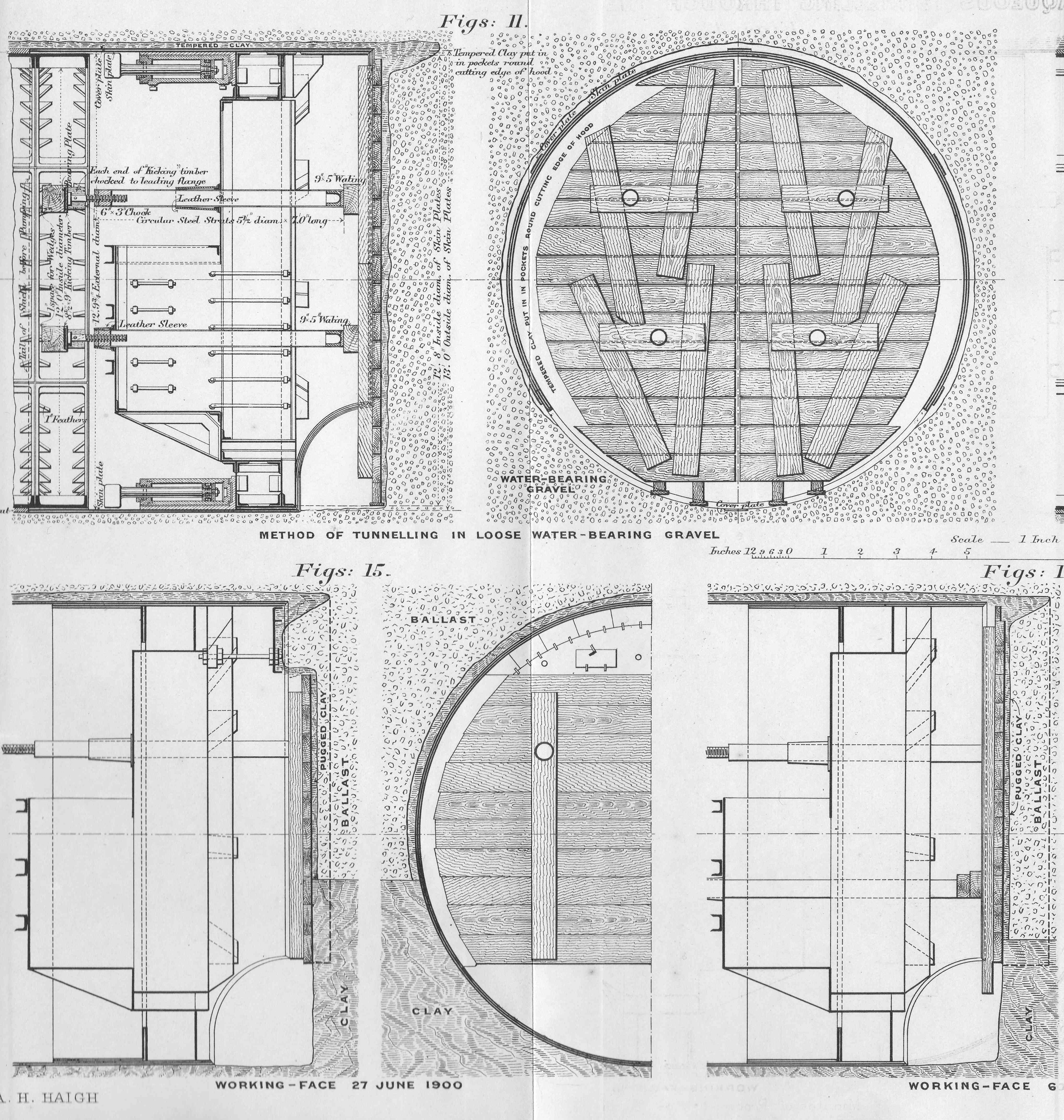
A special shield was constructed, weighing 29.5 tons and with an outer steel cylinder of 13 feet in diameter. The shield included 14 hydraulic rams, each 6 inches in diameter, to push the shield forward as the gravel in front of the shield was excavated.
The following diagrams show some of the detail of the shield’s construction, including the hydraulic rams, their controls and the pipes feeding the rams, along with elevations of sections of the shield. Each hydraulic ram could be operated independently
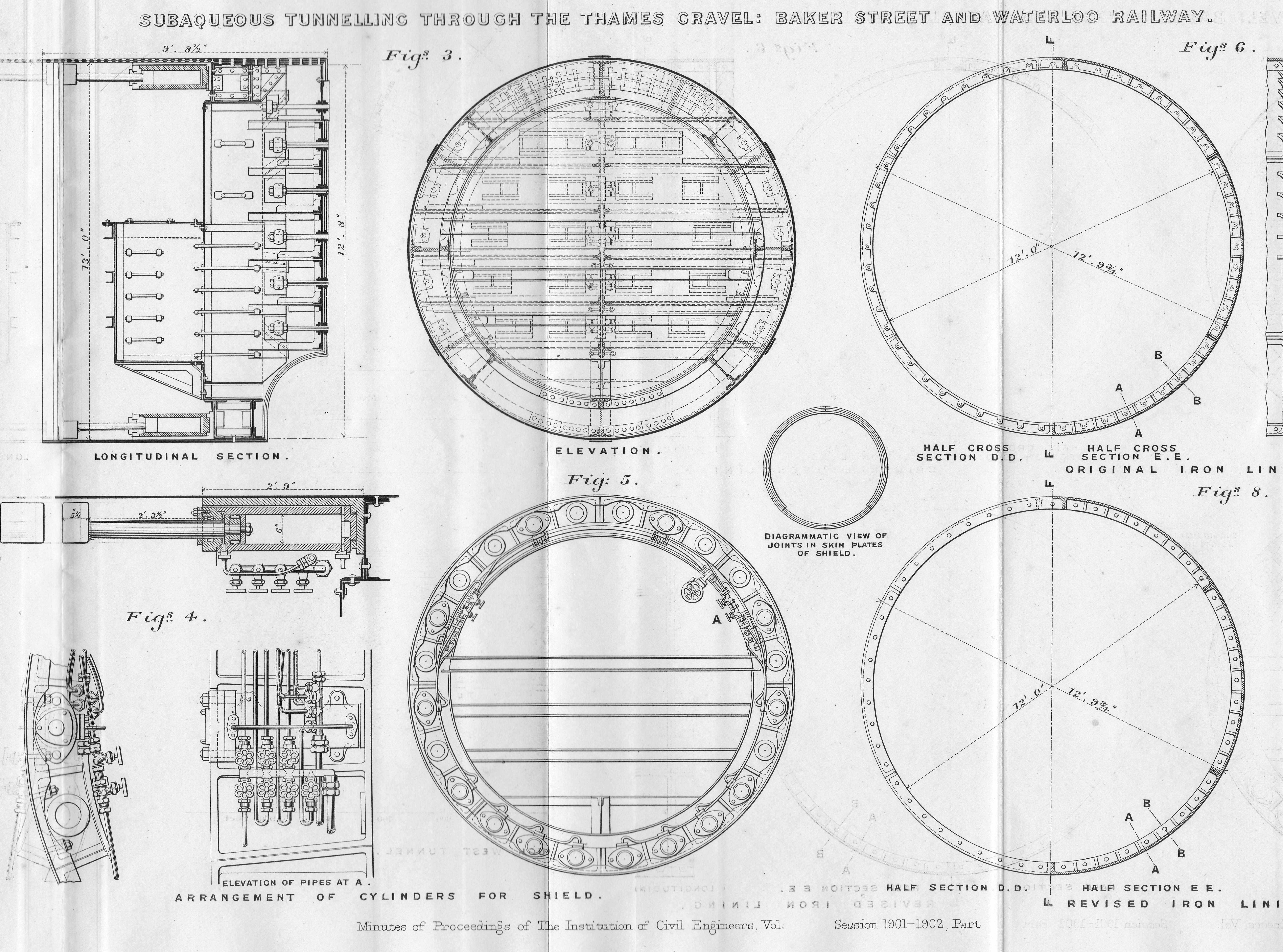
Specially constructed iron rings were designed for the tunnel wall under the river. Each ring was 18 inches wide, and constructed of seven segments. Initially, the joints between the rings were machined to give a smooth fit between rings where bolts were inserted to join the two, however this design was soon revised with rough surfaces on the joints, which were then packed with creosoted pine wood (figures 7 and 9 below).
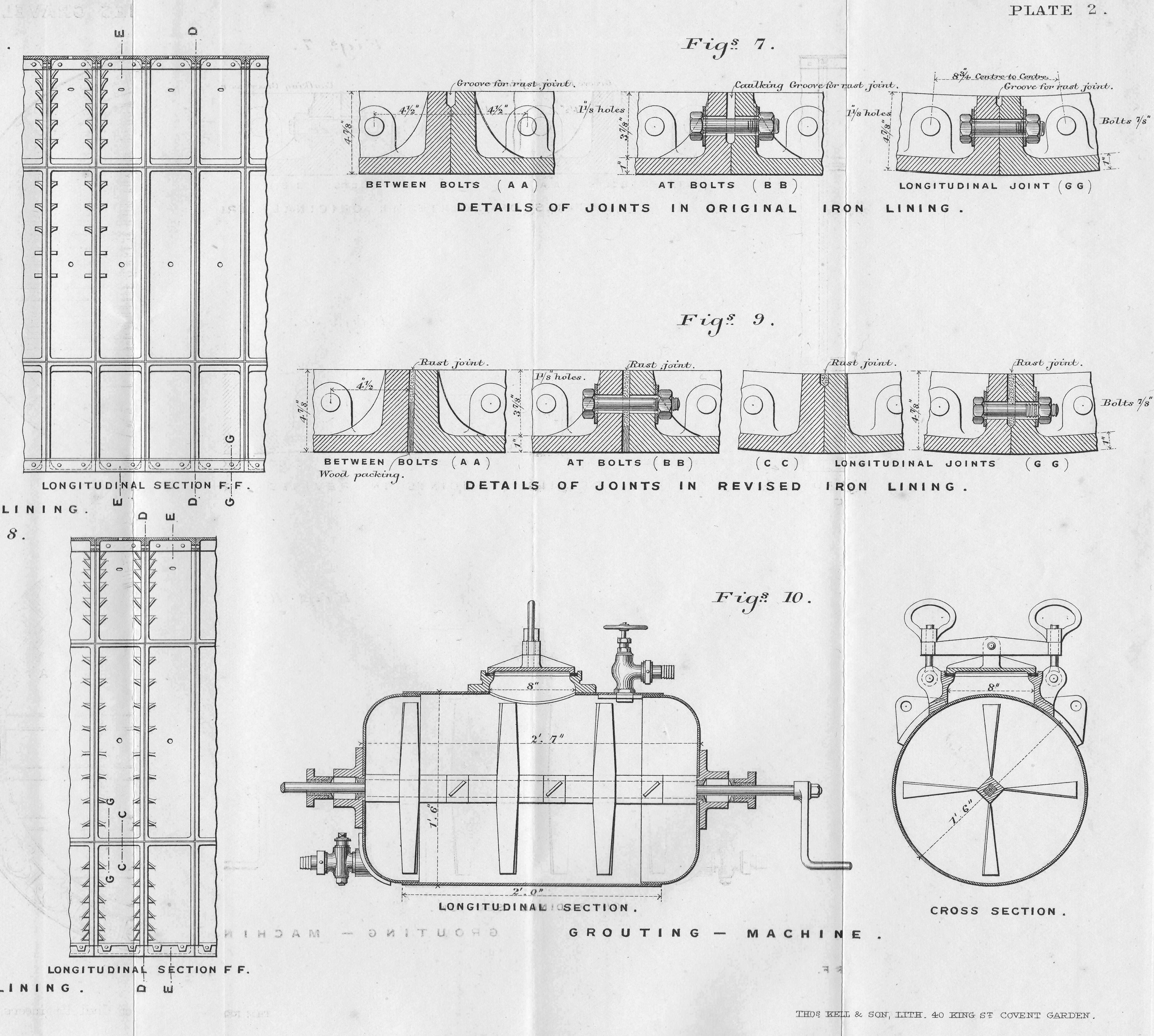
Gaps were grouted using a specially designed grouting machine (figure 10 above), which applied the grout at pressure, through special grouting holes, to help make the rings water tight.
The first part of the tunnel was through London Clay, however as the tunnel approached the centre of the Thames, it hit the water bearing gravel shown in the diagram earlier in the post. This required a change in tunneling method.
Compressed air was now used to keep the tunnel pressure at a level slightly higher than the pressure of the water through which the tunnel was being bored. This prevented water entering the tunnel, but required adjusted working conditions for the workers, with shifts reducing from 12 to 8 hour shifts.
Air pressure was also adjusted as the tide above rose and fell as the pressure of the column of water above the tunnel through the gravel and the river changed.
As the air pressure in the tunnel was higher than the water column, air would escape from the tunnel, up through the gravel, and could be seen by those on the side of the river as water spouts, with the position of the spouts changing as the tunnel progressed across the river.
The configuration of the shield needed to change as the shield approached and entered the gravel. The following drawings show the shield as it approached and then went through the gravel (called ballast in the diagrams).

Work on the first tunnel commenced on the 19th March 1900. it had taken the previous January and February to construct the shield at the bottom of the shaft. On the 2nd of April, work was stopped to allow the construction of an 8 foot thick bulkhead brick wall in the tunnel. This would form the airlock to the section of the tunnel through the gravel where compressed air would be used.
Tunneling restarted on the 2nd of May and on the 6th of June the shield entered the gravel, and on the 15th July, the tunnel was fully within the gravel.
During the period of tunneling through the gravel, there were a few “blowouts” where water entered the space behind the shield. The design of the shield allowed time for the men working to escape, and provided a means of re-entering sections, and continuing work.
On the 27th September, the tunnel re-entered London Clay, with the last of the gravel seen on the 6th October 1900.
Tests were then carried out by removing the pumped air pressure to check for leaks, repairs carried out and compressed air was ended on the 27th October, with the airlock being demolished in November 1900.
The second tunnel was constructed in 1901, with the majority of the same workers, and using many of the lessons learnt on the first tunnel. This second tunnel was completed separately as the shield from the first tunnel was reused.
There were no deaths during construction, two “illnesses” due to working in compressed air, neither of which appear to have been serious. Workers were provided with hot coffee, clean work clothes, and a place to change before and after work. A doctor was assigned to the project to monitor those working in the part of the tunnels with compressed air.
Figure 11 at the top of the following diagrams highlights the method of tunneling in loose, water-bearing gravel:
The Baker Street and Waterloo Railway commenced services in 1906, from Baker Street to Elephant and Castle. The Middlesex & Surrey Express on March the 9th, 1906 provided a description of the new railway:
“The Bakerloo, London’s new tube railway, running from Baker-street to Kennington-road, will be opened tomorrow. There are intermediate stations at Waterloo, Embankment, Trafalgar-square, Piccadilly Circus, Oxford Circus and Regent’s Park, and a novelty about the new stations is that they are each treated in a separate colour scheme.
A uniform fare of twopence for the whole or any distance is to be charged, and trains will run at frequent intervals from half-past five in the morning until twelve thirty at night. The cars are of the usual type, well lighted, and with good, if not excessive provision made for ‘strap-hangers’ and one can imagine a scramble for straps taking place during the busiest hours. Collisions are rendered practically impossible for a most ingenious system, of automatic signaling has been adopted. Should, however, there be a prolonged breakdown, passengers will be able to leave the trains as a lighted footway has been provided between each stopping place along the whole length of the line.
The booking halls at the various stations are almost palatial in their design, and a feature of the lift accommodation is the use of compressed air in the rapid opening and shutting of the gates. All the wood used in construction has been rendered fire resisting”.
What is not mentioned in any of the news reports covering the opening of the Bakerloo is the tunnel under the river, and the challenges that were overcome in building two rail tunnels through water logged gravel under the Thames.
There was speculation at the time that the depression in the clay was caused by dredging for an earlier tunneling project for the Whitehall and Waterloo Railway.
This was a scheme to build a pneumatic railway in an iron tube under the river, the tube being sunk into the river bed rather than bored. The Railway News on the 20th of May, 1865, provided a description of project;
“THE WHITEHALL AND WATERLOO RAILWAY. Arrangements have now been completed which will admit of the commencement of works of this proposed railway immediately on the necessary Parliamentary powers being obtained. The bill has passed the Commons, it is now unopposed in the Lords and in a few days it may be expected to receive the Royal assent.
The railway is to be worked on the pneumatic principle, and is to be carried under the River Thames from Scotland-yard to the Waterloo Station of the London and South Western. The work must, of course, be finished before the wall of the Thames Embankment on the north side is built up, hence the necessity of pushing forward the preliminary arrangements as quickly as possible.
The railway will be formed by an iron tube, twelve feet in diameter, sunk into the bed of the river and supported in piers – a bridge, in fact, built in, not over the waters. the iron tubes will be made by Messrs. Samuda, and the laying of the tube and the other works will be undertaken by Messrs. Brassey and Co. The principle upon which the line will be worked will be much the same as that adopted on the experimental railway in the grounds of the Crystal Palace. The machinery will be on the Surrey side at the York-road Station.
The whole of the works will be completed in twelve months from the date of commencement. The cost of the undertaking will be about £130,000. The total weight of iron in the tube will be about 5,000 tons, and it will be sunk in four separate sections.”
The project soon ran into financial difficulties, the proposed timescale and costs for the project were hopelessly optimistic. In February 1868, papers were reporting that “The Whitehall and Waterloo Railway is at a complete standstill, and the directors advise the abandonment of the concern, unless, as they say, something turns up between this and the spring. They, of course, hope the South Western will help them in their difficulty, but one would think nothing could be farther from the thoughts of the directors of this company.”
In 1871, the company formed to build the Whitehall and Waterloo Railway was wound up.
The route of this earlier railway did follow much the same route as the later Baker Street and Waterloo Railway, and some parts of the iron tube were found during excavation for the construction of the Shell Centre complex, however I am not sure whether the depression in the London Clay was caused by dredging for this abandoned project.
The shape looks natural, the plan was to dig in the tunnel across the river to bury the iron tube, however the PLA chart shows the change in depth running along the river.
Whether natural or man-made, it was a considerable achievement to bore two tunnels that would become the Bakerloo line, through water bearing gravel, under a considerable head of water, at the start of the 20th century.
If you travel from Embankment Station to Waterloo on the Bakerloo, you will pass through this area of gravel soon after leaving the station.
Interesting piece. Between Oxford Circus and Piccadilly Circus the line follows the curve of Regent Street exactly because lines had to be directly underneath roadways in order to avoid the necessity of paying easements to property owners. This curve is actually too tight for tube trains to handle comfortably, resulting in speed restrictions on that section of line.
Thank you for another fascinating piece. I’m wondering how the rolling stock was loaded into the tunnels – there seem to have been no open air sections of track.
They were delivered, by horse and cart, from the LNWR’s depot to the BS&WR’s new depot at St. George’s Cross/London Rd that is still in use by the Bakerloo line via a shot section of connecting tunnel that rises to the surface. They’d arrived there from the American Car & Foundry Co, PA, having been shipped over in kit form, assembled in Trafford Park, Manchester, and hauled south by the trainload behind LNWR steam locos!
London Road depot is above ground.
No, the depot is about 15 metres or so below ground but is not built over.
Fascinating as ever! As noted on Twitter I’ve posted a link to some pages fromt he opening brochure that may interest & that includes an image of the staging in the river along with what looks like a blow out that I hope did not happen! I’ve never seen reference to such an incident but it did happen elsewhere.
The under River tunnels at Embankment/Waterloo, of the Bakerloo and the Northern (both ‘original’ terminal loops and Kennington Extension) have an interesting history regarding wartime security and maintanence, given the relative shallowness of the tunnel tubes under the river bed. In WW1 the Bakerloo tunnel was relined in a complex project to strengthen the bore and embarrassingly this had to be re-engineered due to effective failure late in WW2. During that latter conflict, like all cross-Thames tube tunnels, massive closures for fitting of floodgates occured. In recent years the line of the tunnel has again had additional works. Best caught up with in the excellent “Rails Throughthe Clay”, 2nd ed, by Croome & Jackson.
“The route of the Whitehall and Waterloo railway did follow much the same route as the later Baker Street and Waterloo Railway, and some parts of the iron tube were found during excavation for the construction of the Shell Centre complex”.
Thomas Webster Rammell’s pneumatic railways are a particular interest of mine – see http://www.xenophon.org.uk/rammell.html. I have heard vague references to remains being found in the excavation for the Shell Centre, but no concrete proof. Can you provide a reference please?
Thanks for a fascinating post.
Thankyou for another fascinating post! I have ever more respect for the engineers and the draughtsmen who produced the plans, right through to showing the concentric rings in the wooden elements. We too easily forget the ingenuity and plain hard work – and danger – that went into what we now take for granted. Whenever the train passes through a particularly tight curve and the wheels squeal, we don’t consider the reasons. Wonderful stuff. Many thanks. Richard T
Fascinating article as always – you research so thoroughly to provide us with this information, so many thanks to you and a Happy New Year.
A very interesting piece, Admin. I think I may cross my fingers next time I use that section of the tube !
I would also like to wish you a Happy New Year and many more posts for us to read. Thank you.
The depression in the London Clay may be the result of the Thames flowing at a lower level during the Pleistocene (the ice age). Sea levels were much lower and the Thames flowed at a much lower level at times. It was beyond the ice front but changed its course in consequence of the huge volume of melt waters flowing from the ice cap to the north. One example of the result of this is the Blackwater Estuary in Essex – a former channel of the Thames. After the Pleistocene sea levels rose and river channels filled with river deposits – frequently gravel.
Having said all that I have no evidence that this particular depression was formed in this way but it is a strong possibility. We see the Thames as a fixed feature but it has been a very dynamic and geographically mobile one until very recently.
Excellent piece as ever – thank you! And no prizes for guessing what I read at uni!
An excellent insight into the tunnelling methods of the early 20th century which is taken for granted by many. Could I just make a couple of observations?
At Oxford Circus, the Bakerloo line is, in fact, 4 metres above the Central line. However, there is a much tighter clearance between the Bakerloo and the Post Office Railway. I recall taking a trip along the length of the PO Railway while working for Crossrail in the 1990s. On our way back to Mount Pleasant, the driver stopped the train in the pitch dark tunnel and we were told to be silent. Very soon we heard through the darkness a Bakerloo line train approaching, the doors opening and then closing after which the train departed. A very weird experience.
The line opened as the Baker Street & Waterloo Railway in March 1906 between Baker Street and Kennington Road (now Lambeth North) and was extended to Elephant & Castle in August 1906. Meanwhile, its name was changed to Bakerloo in July 1906.
Looking forward to many more of your fascinating articles.
Thanks Trevor, that must have been a fascinating experience on the Post Office Railway.
The 6 inch clearance is stated in the 1902 booklet, and it did seem remarkably close for the tunneling technology of the time. Agree with you about taking early 20th century tunnelling methods for granted. The accuracy that was achieved without the technology and tunnelling machines we have today is remarkable.
As a lead tunnel engineer for LU at one time I recall this section of the Bakerloo Line needing maintenance and grouting. A well researched and interesting article on the construction of this tunnel under the Thames.
Nice article!
There’s lots of information around regarding “drift filled hollows” – natural geological formations with a range of possible causes. For example:
https://www.geolsoc.org.uk/~/media/shared/documents/groups/specialist/engineering/History%20of%20Rock%20head%20anomalies%20in%20the%20London_V1.pdf?la=en
Tunnelling under a river in compressed air was exceptionally dangerous and you have to salute the men who did it.
I’m really happy to have found this article. We have recently been looking at carrying out maintenance on old gravestones inn Manchester and Sale, from our forebears, which has led us to new information for our family tree. One Frederick R Wainwright 1875-1905) turned out to be the Medical Officer for the tunnel works you describe. His article published in the Lancet 22 Dec 1900 describes his observations on compressed air sickness. He documents 47 cases during the period required for the drilling and no fatalities: previous similar works had experienced loss of several men. This was at a time when the symptoms of joint pain were just beginning to be attributed to gases forming bubbles in the tissues as the person returns to normal pressure; Wainwright used a decompression chamber to good effect and his work contributed to present day understanding. He recognised the risk factors of body weight and alcohol use and records a lack of evidence to support suggestions that men should be prevented from exercising or that temperature is a factor.
This Wainwright is the son of William Wainwright, born in Manchester, eventually vice president of the Grand Trunk Pacific Railway in Canada, after whom the town of Wainwright was re-named following his death.
https://www.thelancet.com/journals/lancet/article/PIIS0140-6736(01)99733-8/fulltext