Category Archives: Under London

The Temple of Mithras and Vine Street Roman Wall

The City of London has been occupied in one form or another for around 2,000 years, and those centuries of occupation have left their mark, whether it is in the pattern of the streets, pushing the embankment wall into the river and reclaiming parts of the foreshore, churches, rising ground levels, and the buried remains of buildings along with the accumulated rubbish, lost possessions, burials and industrial waste of the centuries.

In today’s post, I am visiting two places where the remains of Roman occupation are on display. two very different structures and methods of display, but each telling a story of London’s long history, and how these remains have survived, and their discovery, starting with:

The Temple of Mithras

The Temple of Mithras was one of the major post-war discoveries in the City of London as archaeologists rushed to excavate sites, although they had very limited funds and time.

The Temple of Mithras tells an interesting story of Roman occupation of the City, post-war archaeology, and how we value such discoveries.

The Temple of Mithras is now on display at the London Mithraeum, built as part of the construction of Bloomberg’s new European headquarters.

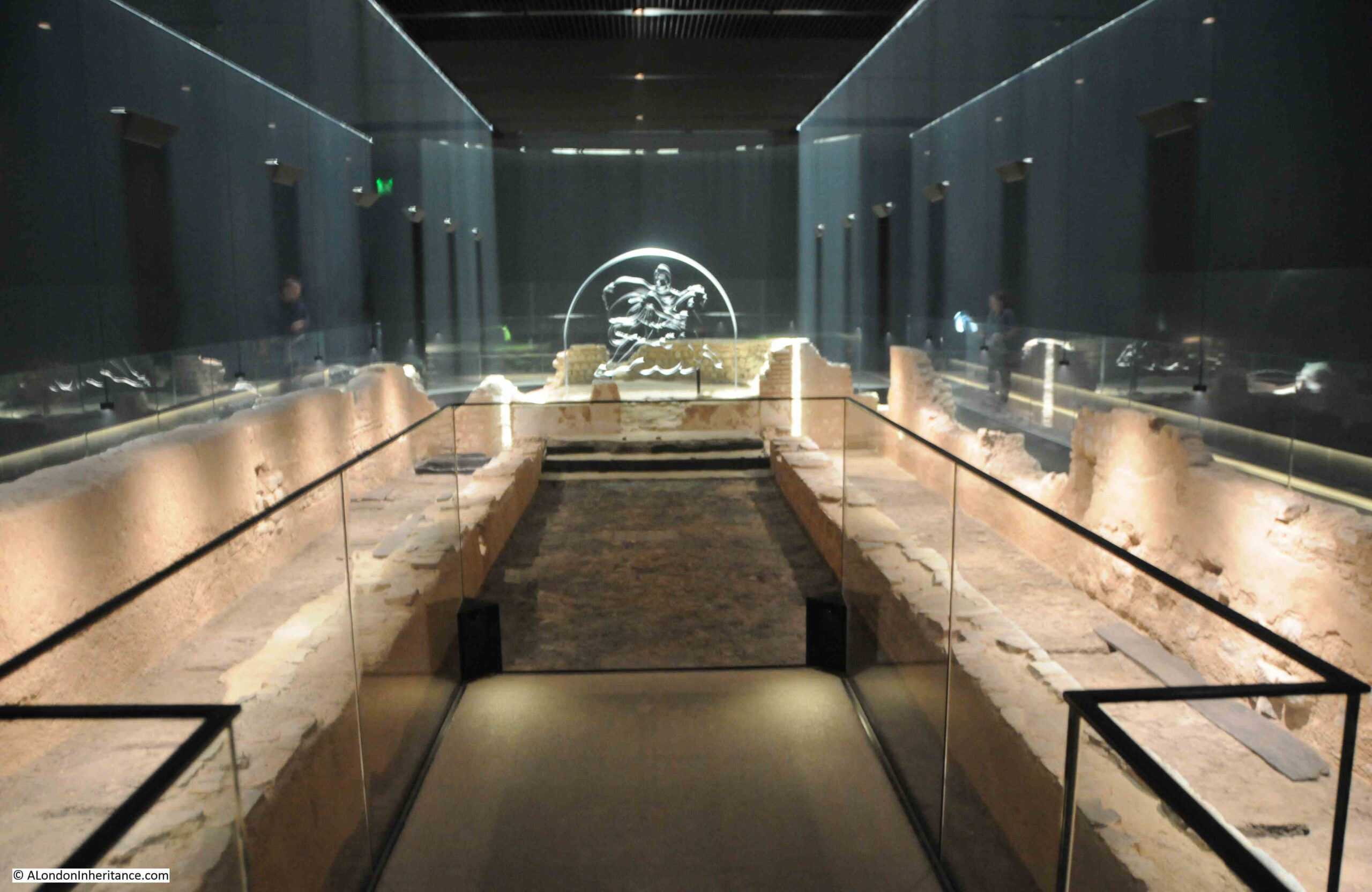
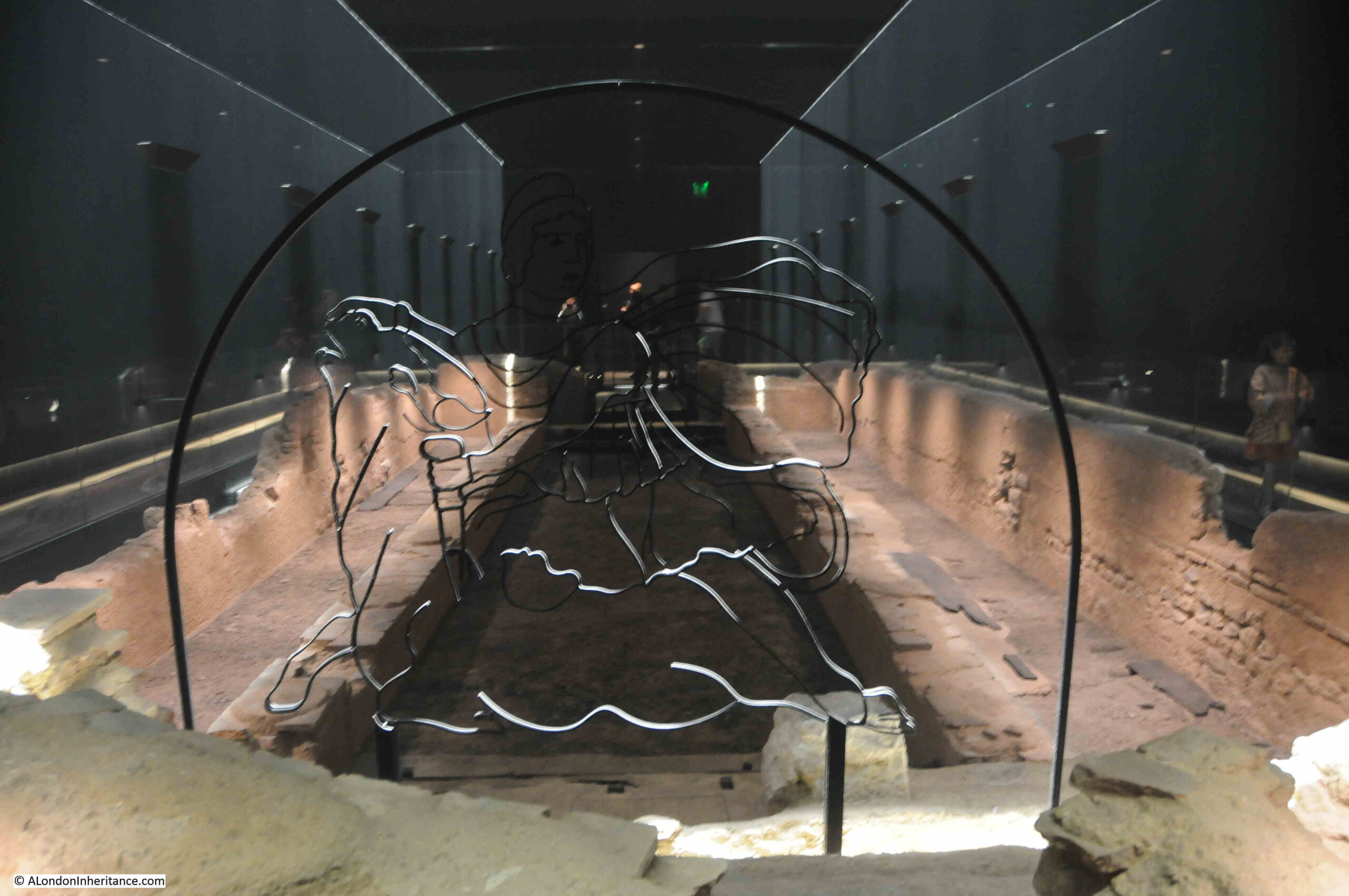
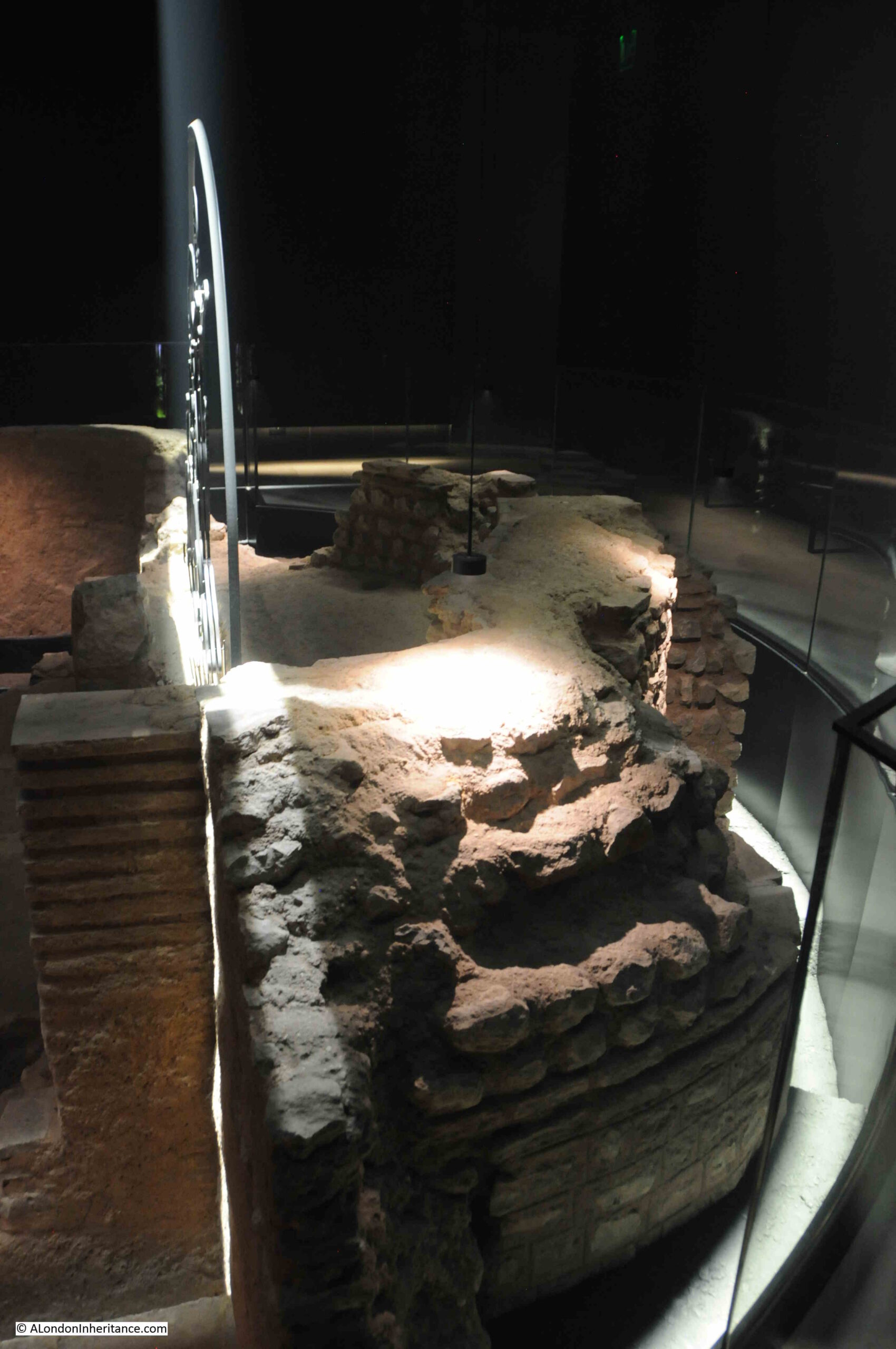
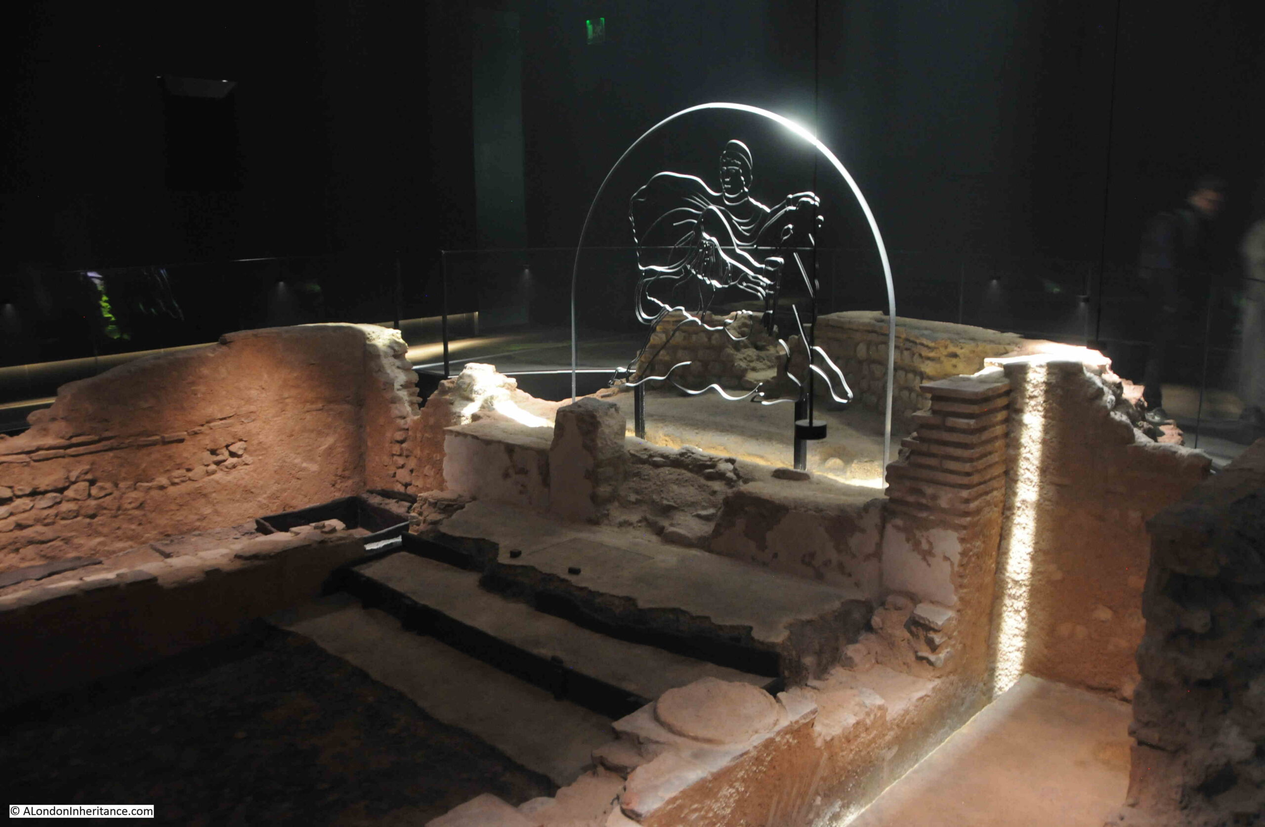
The remains of the temple have been displayed in a really imaginative way. Subtle lighting, a recreation of the sounds of activity in the temple during the Roman period and an image of the god Mithras overlooking the temple from the location of the apse and the block where the final altar in the temple was located.

The view on entering the Temple of Mithras:
Temple of Mithras

The Temple of Mithras was discovered in 1954 by the archaeologist W.F. Grimes.

The post-war bomb sites across the City of London offered a one off opportunity to excavate and explore for remains of occupation of the City from previous centuries, and in 1946 the Society of Antiquaries of London sponsored a short trial session, and then established the Roman and Mediaeval London Excavation Council in order to more formally establish a long term series of excavations.

These continued through to December 1962, with the majority being led by W.F. Grimes.

There were two main challenges to this work, both of which almost resulted in the failure to discover the Temple of Mithras – money and time.

The Excavation Council was able to raise funds from private donors, and in 1968 Grimes published “The Excavation of Roman and Medieval London”, a brilliant book providing an initial record of the work between 1947 and 1962. In the back of the book is a list of donors, which included the Government Ministry of Works (£26,300) and the Bank of England (£2,750) as the top two donors, down to two pages of donors who contributed £1. There were also a large number of donors who gave less than a £1, but were not recorded in the book.

By 1954, donor funds were growing short, and in the many newspaper reports of the discovery, it was reported that “Mr. Grimes had only found the temple because, after private subscriptions fell off, a grant from the Ministry of £2,000 a year had kept him going”.

There was also the challenge of time, and the walls of the temple were found towards the very end of the period agreed with the developer to excavate the site. Such was the importance of the find, that the developers allowed an extra two weeks for excavation.

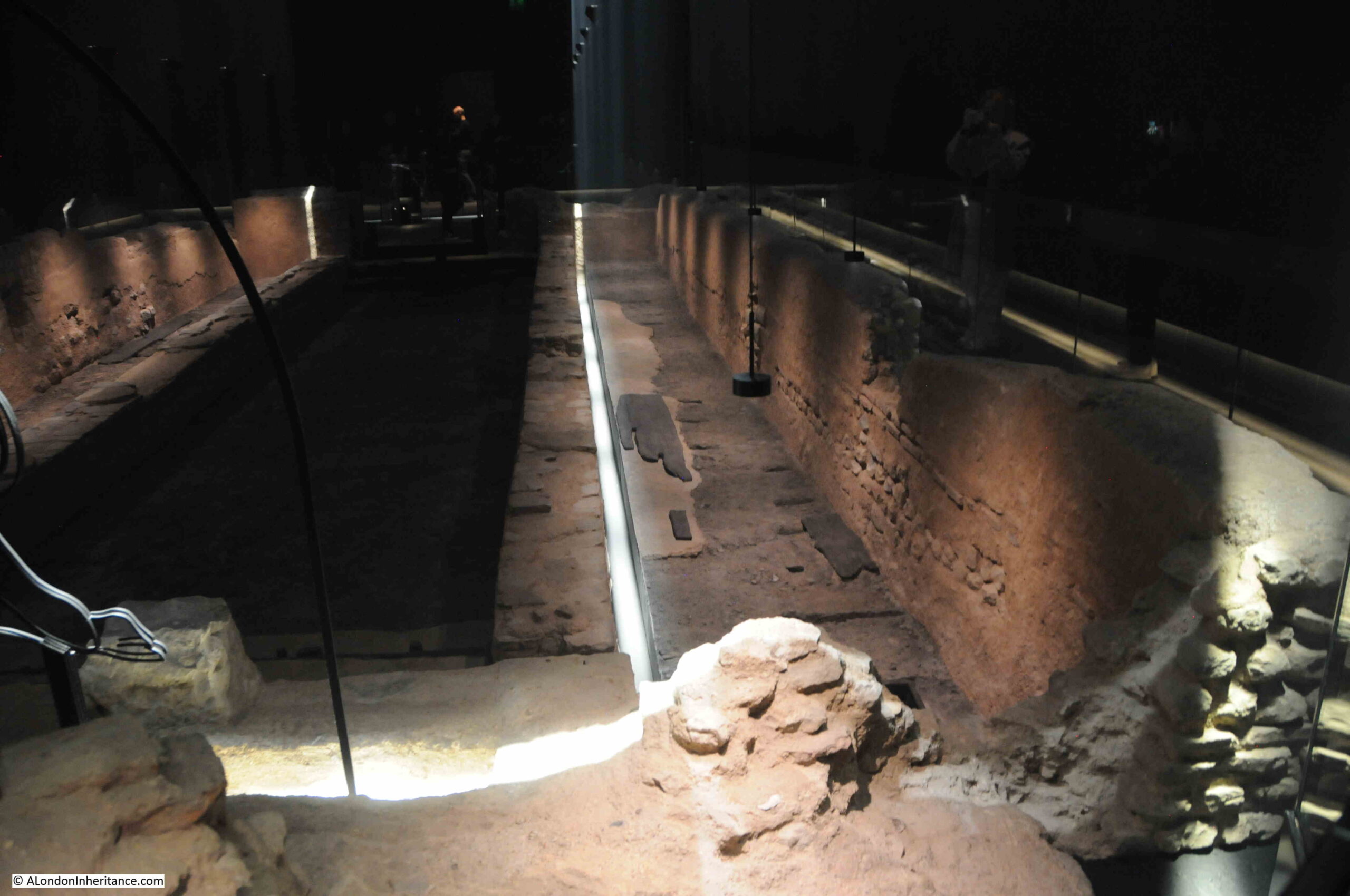
At the temple today, there are two walkways along the sides of the temple, and at the end of these, we can look back at the interior of the temple:
Temple of Mithras

From the location of the apse, and where the altar was located:
Temple of Mithras

The area that was being excavated, and where the Temple of Mithras was found, was a large almost triangular plot bounded by Queen Victoria Street in the north, Budge Row to the south and Walbrook to the east. Budge Row sort of exists, but is now a covered walkway between two sections of the Bloomberg building, and appears to be called the Bloomberg Arcade.

The importance of the site was that it was part of the valley of the old Walbrook stream, and at the time, very little was known of the extent and nature of the stream and the surrounding valley.

Prior to the temple being found, work had focused on identifying the location of the stream, and sectional cuts were taken across the site which found that the Walbrook was in a shallow basin of around 290 to 300 feet across, and that the stream was around 14 feet wide and relatively shallow.

Excavations also found that the process of raising the land surface had started at a very early date, with dumping of material in the basin of the stream, mainly on the western edge of stream.

A number of timber deposits were found, mainly floors, and also contraptions such as guttering, all to deal with the wet conditions of the land surrounding the Walbrook stream.

There were very few stone structures, and apart from the temple, only one other stone building was found on the site, so although the site was in the centre of Roman London, it was very different to what could have been expected, with no concentration of stone buildings, and probably an area which had a stream running through, and was wet and marshy.

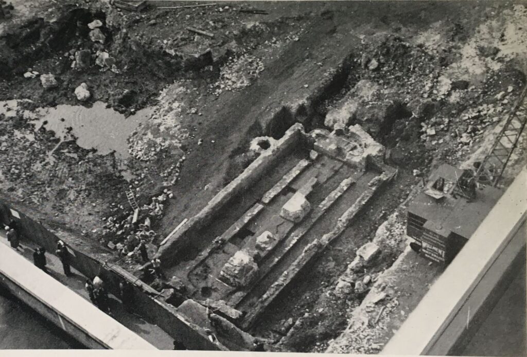
The main body of the temple was found to be rectangular and around 58.5 feet long and 26 feet wide, and consisted of a semi-circular apse at the western end.

In Grimes book, he mentions that the eastern end of the building consisted of a narthex or vestibule, which projected beyond the side walls of the building, and that part of this vestibule lay, and in 1954 at the end of excavation, remained under the street Walbrook. I need to find out if that is still the case, or whether it has since been excavated.

Photo from the book “The Excavation of Roman and Medieval London” by W.F. Grimes showing the Temple of Mithras as finally excavated. The photo was taken from the north east, so would have been next to the street Walbrook:
Temple of Mithras

The photo below is a view of the apse, which was at the western end of the temple, the upper right of the temple in the photo above:
Temple of Mithras

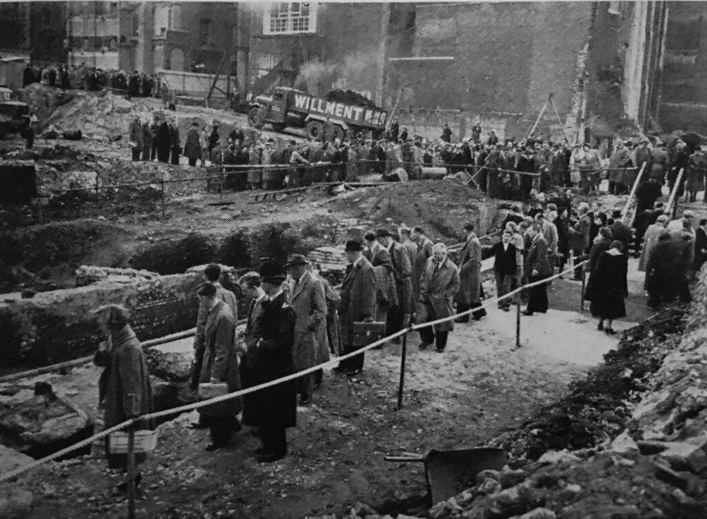
The excavated temple was opened to the public for a short period between excavation and the removal of the stones, and very long queues formed to get a glimpse of this Roman survivor:
Temple of Mithras

However, you can forget all the stories of polite British queuing, as the News Chronicle reported on Wednesday the 22nd of September 1954: “Sightseers Storm the Cordon. When darkness came, hundreds were still queuing. They got angry and dozens stormed through police barriers to see the Temple of Mithras.

Instead of the 50 to 500 people expected at the half acre bomb site near Mansion House, where last week a marble head of the god was unearthed, there were 10,000.

Police reinforcements were called as they milled around. At 6:30 when the site was due to close, thousands were still queuing. Then the contractors – who are to build London’s tallest office block on the site – decided to keep it open till seven.

There was an angry scene when the police announced half an hour later that no more people could be allowed. By then, darkness was falling and hundreds were still queuing. The disappointed crowd shouted ‘We’ve been waiting more than an hour’.”

Looking back at the apse:
Temple of Mithras

There were a number of finds at the site of the temple, including, Mercury, a messenger god, seated on a ram:
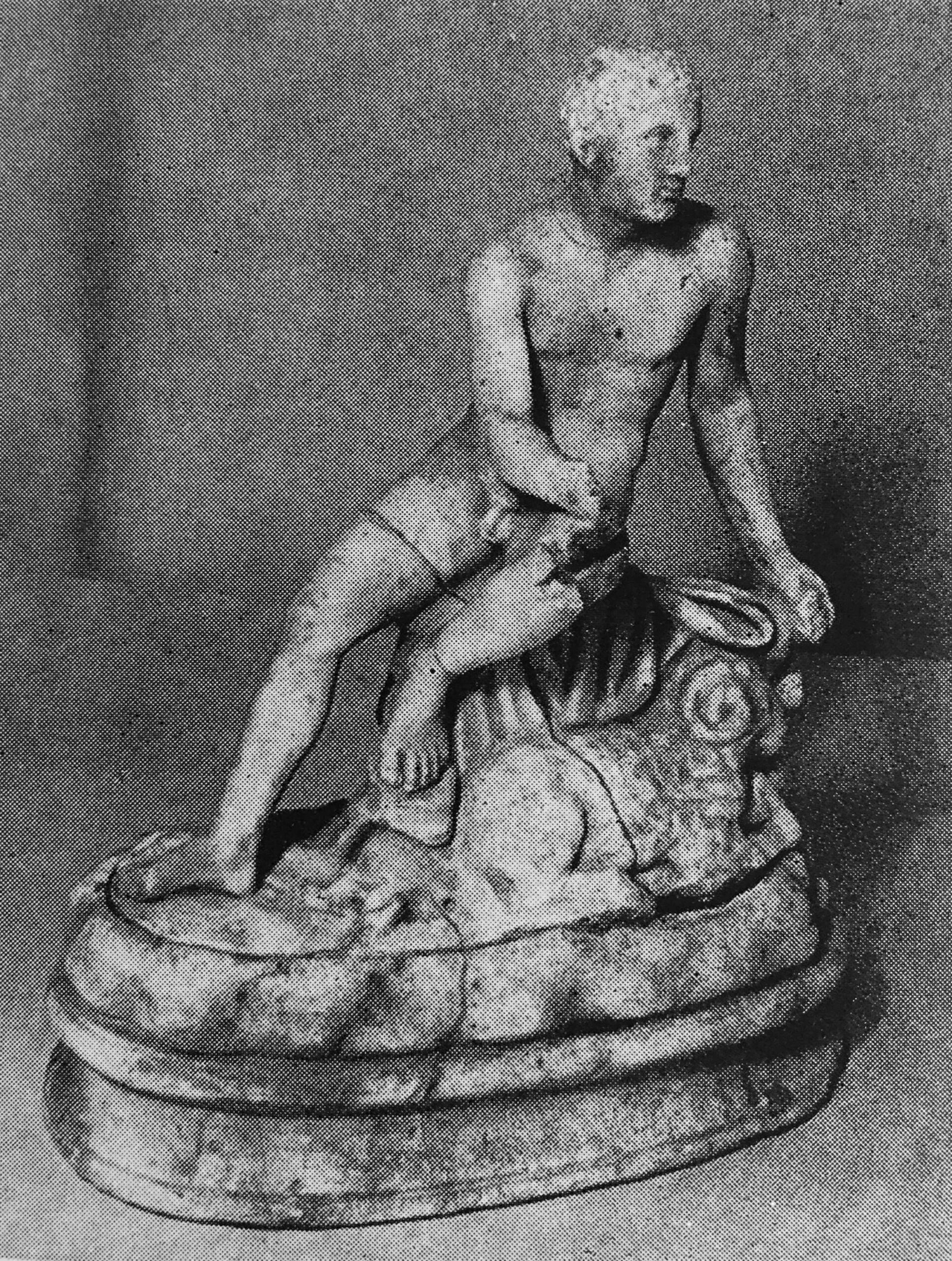
Temple of Mithras

Mable head representing the godess Minerva:
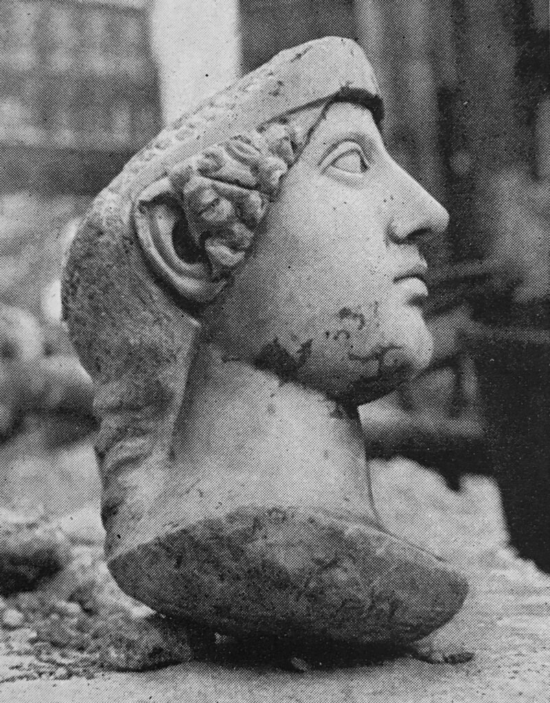
Temple of Mithras

And then there was the head and neck of Mithras. This was found by one of the excavators on the site, Mrs. Audrey Williams, and I found a photo of her, holding the head of Mithras, in the book “Buried London” by William Thomson Hill (1955):
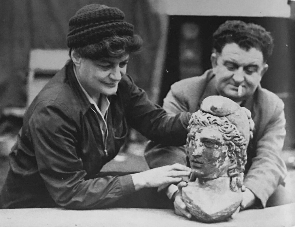
Temple of Mithras

Audrey Williams was a highly experienced archeaologist, but was, and still is, rather unrecognised.

She was mentioned in some newspaper reports about the temple, a typical report being “Excavators were about to put aside their trowels when Mrs. Audrey Williams, second-in-command to Mr. W.F. Grimes, director of the London Museum in charge of the excavations, scraped the side of a marble cheek”.

There is a biography of Audrey Williams on the excellent Trowel Blazers site, which also records that it was Audrey who was on site every day, and her work makes up much of the archive as Grimes was also working on another site.

Mithras was one of many Roman gods, and the cult of Mithras started in Rome and eventually spread across the Roman empire. It seems to have attracted those who were administrators, merchants and soldiers within the empire, and meetings were held in temples, often below ground. Dark, windowless places, which the presentation at the London Mithraeum demonstrates well.

The location of the temple, on the banks of the Walbrook stream would have added an extra dimension to the place.

At the end of the time available for the excavation, there was concern about the future of the temple, and whether the cost of preserving or moving the temple would be supported by the Government. A solution was found thanks to the owners of Bucklersbury House, the building that would be constructed on the site, as reported in the Courier and Advertiser on the 2nd of October, 1954:

“The Temple of Mithras, recently uncovered in the City of London, is to be moved, brick by brick, and re-erected on a site 80 yards away.

A Ministry of Works statement yesterday said – It has been decided that the cost of preserving the remains of the Temple of Mithras in its present position, estimated at more that £500,000 cannot be met from public funds. Happily, however, Mr. A.V. Bridgland, and the owners of the site of Bucklersbury House, have made a most generous proposal, which the Government believe will be widely welcomed.

The temple is to be moved from its present low level and put up again in an open courtyard on the Queen Victoria Street front of Bucklersbury House site.

Estimated cost of the removal is £10,000 which is to be borne by the owner of the site.”

Photo from the book “Buried London” by William Thomson Hill (1955), showing the Temple of Mithras being rebuilt in its temporary location in October 1954 before being moved to Temple Court in Queen Victoria Street where it was put on open air, public display in the early 1960s:
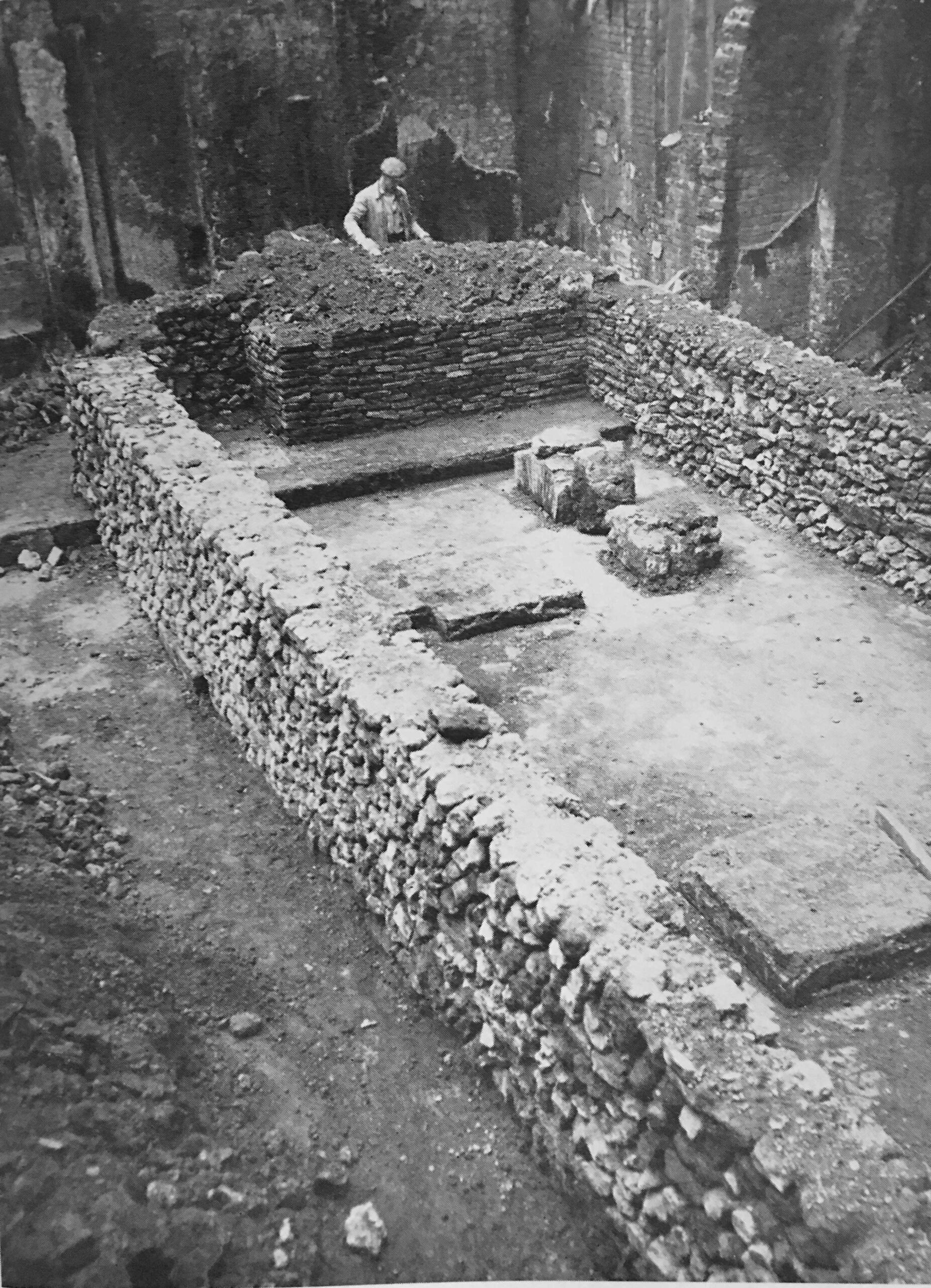
Temple of Mithras

It is interesting to speculate just how original many of these early buildings remain.

Grimes, in his book states that the individual stones of the temple were not numbered, rather the walls were photographed and the rebuild of the temple was based on these photos.

The reconstruction in the London Mithraeum also used new mortar between the stones, but using a formula which would have been used at the time..

The Temple of Mithras remained in the open until the Bloomberg building was constructed on a large site, which included the location of the post-war Bucklersbury House.

The Temple of Mithras is not in exactly the same position as when discovered as it is a small distance to the west, but it is close enough, and at the level below ground to its original location.

There is also an exhibition of many of the finds from the site, including a steelyard balance and weights, used for measuring the weight of goods which would have been suspended from the hook on the right:
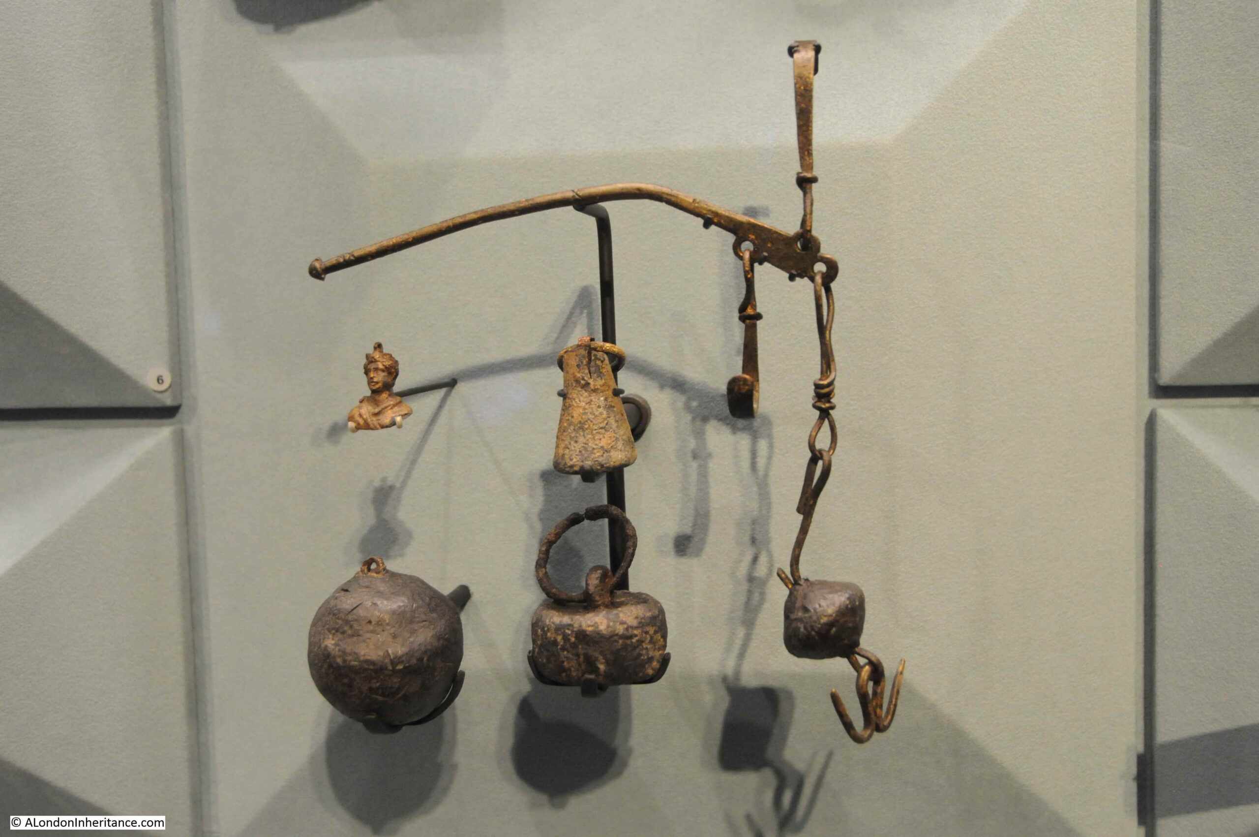
Temple of Mithras

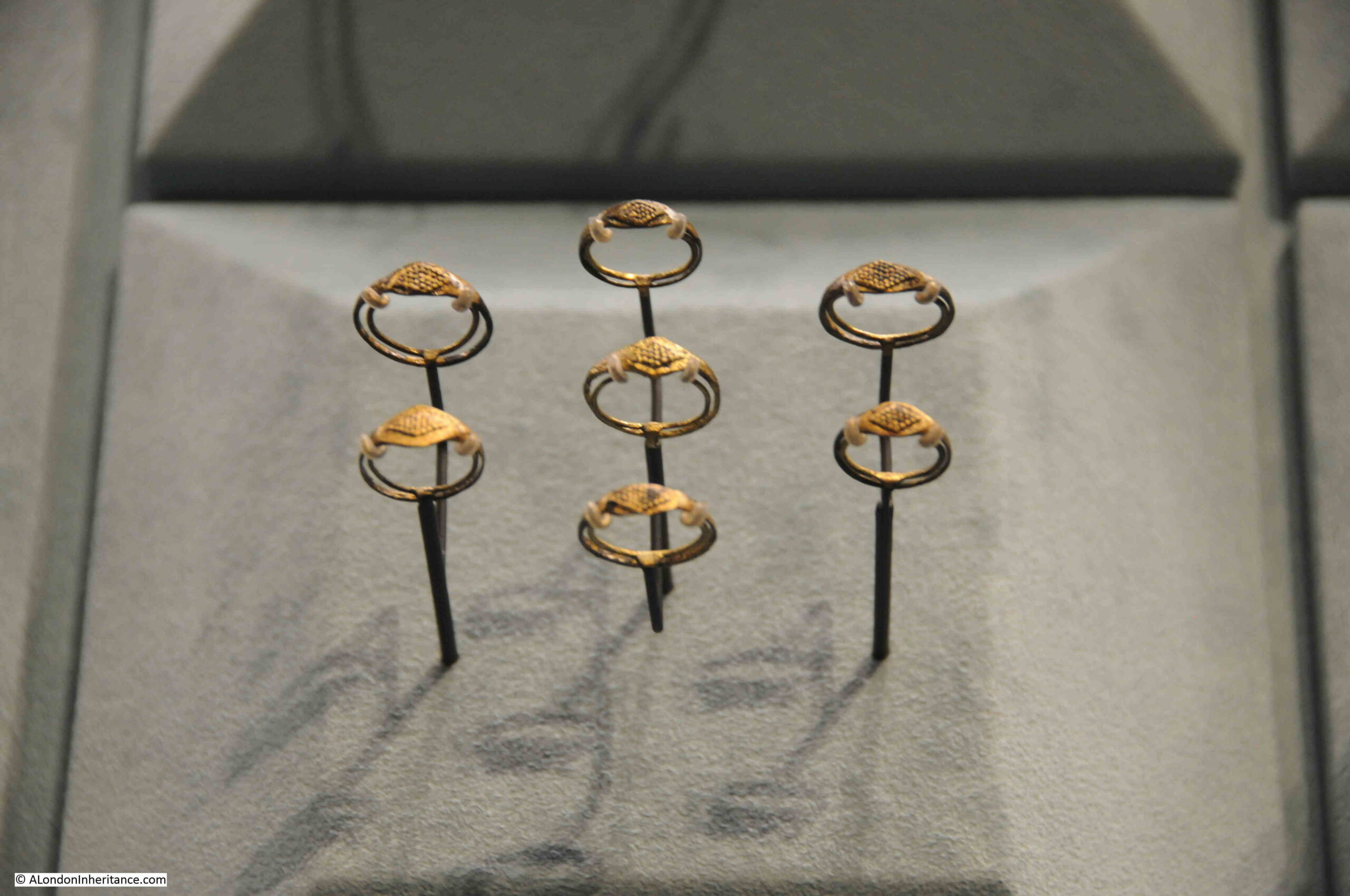
And rings:

Temple of Mithras

The Temple of Mithras is well worth a visit. As well as the physical remains of the temple and finds from the site, the presentation as part of the London Mithraeum provides a good impression of how the temple may have been used, when it was sitting on the banks of the Walbrook, some 1800 years ago.

Details can be found at the site of the London Mithraeum, here.

There is a British Pathe film of the discovery here.

There is an absolutely fascinating lecture by Sadie Watson on the Return of the Temple of Mithras in London, part of the Gresham College series of lectures. It can be found here.

The Vine Street Roman Wall

The City Wall at Vine Street is the name of a new exhibition of part of the Roman London wall in the basement area of a new building complex that seems to consist of student accommodation and offices.

Although the name of the exhibition includes Vine Street, the entrance is at 12 Jewry Street. The overall building complex sits between Jewry Street and Vine Street.

After entering at ground level, a walk down to the lower level reveals the section of London wall:
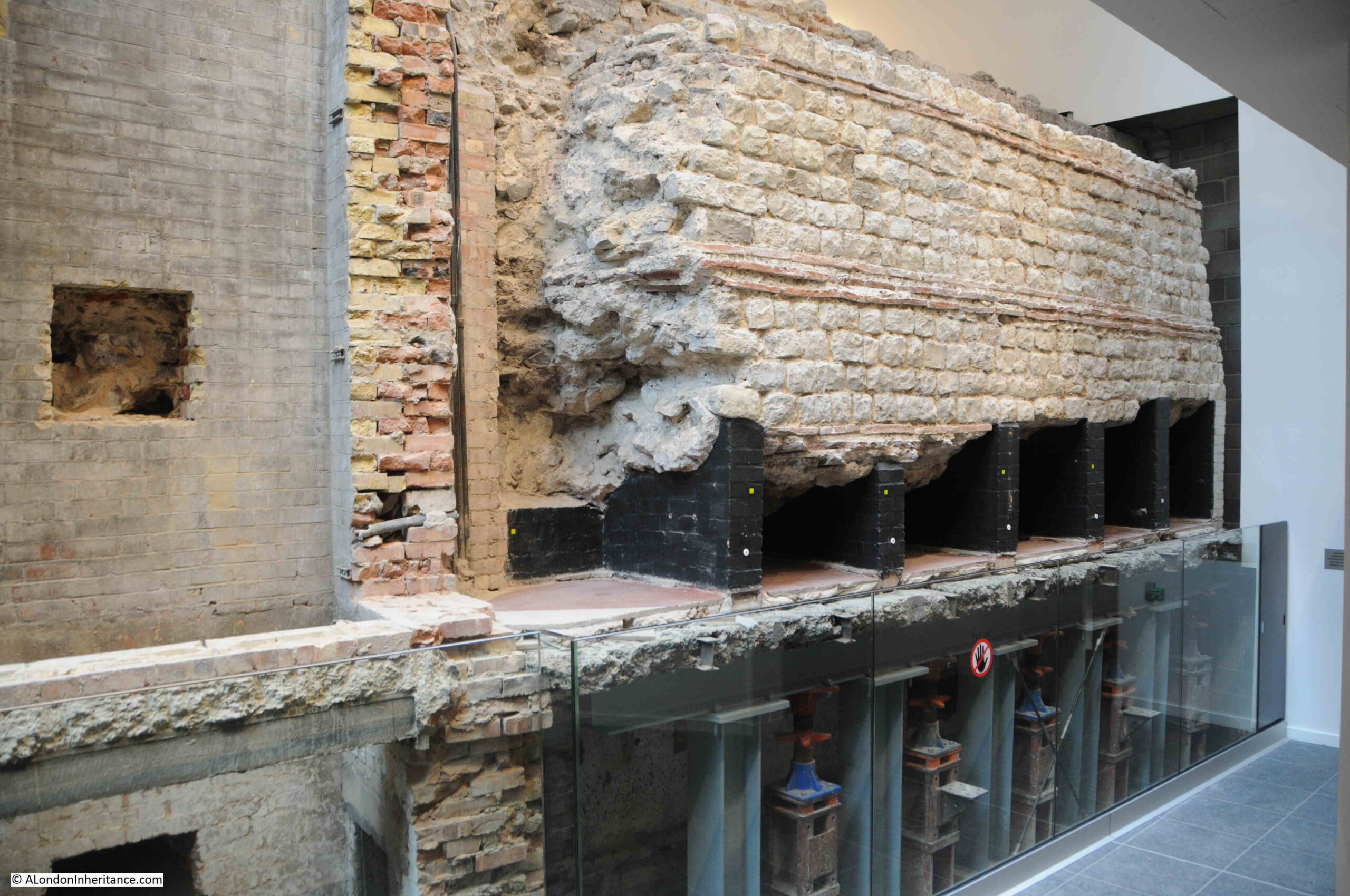
Vine Street Roman Wall

The face of the wall in the above photo is the side that was on the inside of the City of London.

The presentation of the wall is really very good, because it shows not just the Roman wall, but also tells the story of how it has survived for so long.

Today, in preparation for a new building, the existing building on the site is usually fully demolished, down to a big hole in the ground. The new building is then constructed without any use of parts of the structure of the previous building.

This is starting to change, for example the old BT building on Newgate Street is being completely remodeled, and the building’s structural frame will be mainly retained in a building that will look completely different from the outside.

In the past, where there were existing walls, it was often very cost effective to incorporate these into a new building. I have written about a couple of examples in previous posts such as St. Alphage on London Wall, the Bastions and Wall between London Wall and St. Giles, Cripplegate, and the Roman Wall on Tower Hill, and it was only by being included in much later buildings that these earlier structures have survived.

The Roman Wall did continue in use during the medieval period, when medieval brick and stone work extended the height of the wall as the ground level in many parts of London was gradually rising, but it was becoming redundant.

The City was expanding outside the wall, so although parts were demolished and stones often reused as building material, other parts of the wall were built against, and included in new structures, and the section on display became part of a number of buildings on the site.

In the construction of a new building on the site in 1905, the wall was exposed, and thankfully it was preserved in the basement.

In the above photo, the black piers supporting the wall are from the 1905 construction, and underneath are jacks installed as part of the build of the current building on the site.

And to the left of the Roman wall in the above photo, and more clearly in the photo below, can be seen the walls of the last building on the site, and how they butted up to the Roman wall:
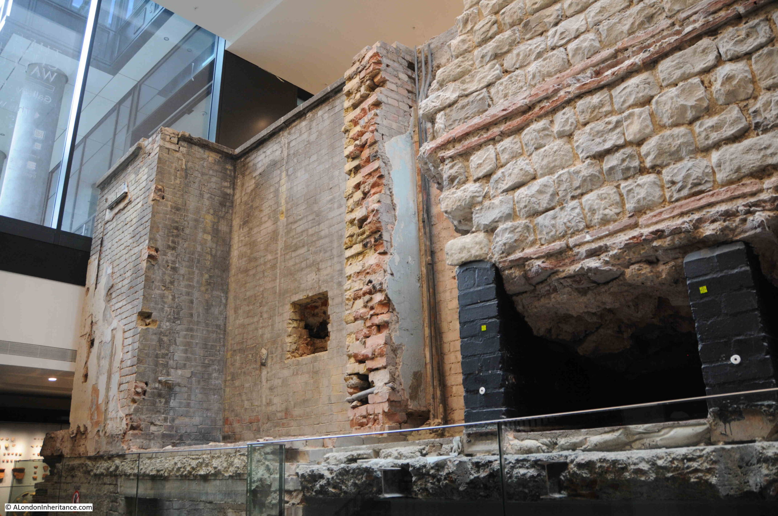
Vine Street Roman Wall

Walking to the other side of the wall and we are now presented with the wall that would have faced outside of the City:
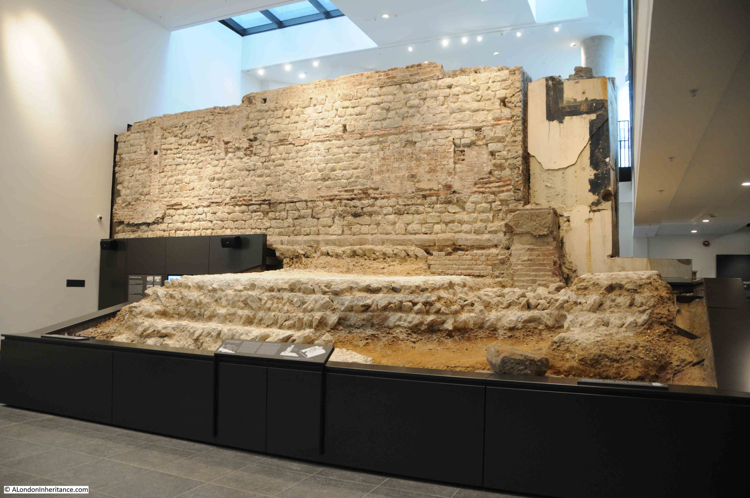
Vine Street Roman Wall

And we can also see the remains of a bastion, a small building on the side of the wall, usually with a semi-circular end, that was used for defensive purposes:
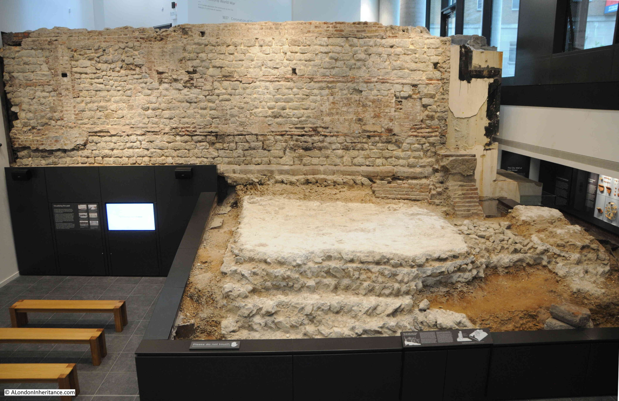
Vine Street Roman Wall

As with the London Mithraeum, there is a large display of the many finds from the site and surrounding area:
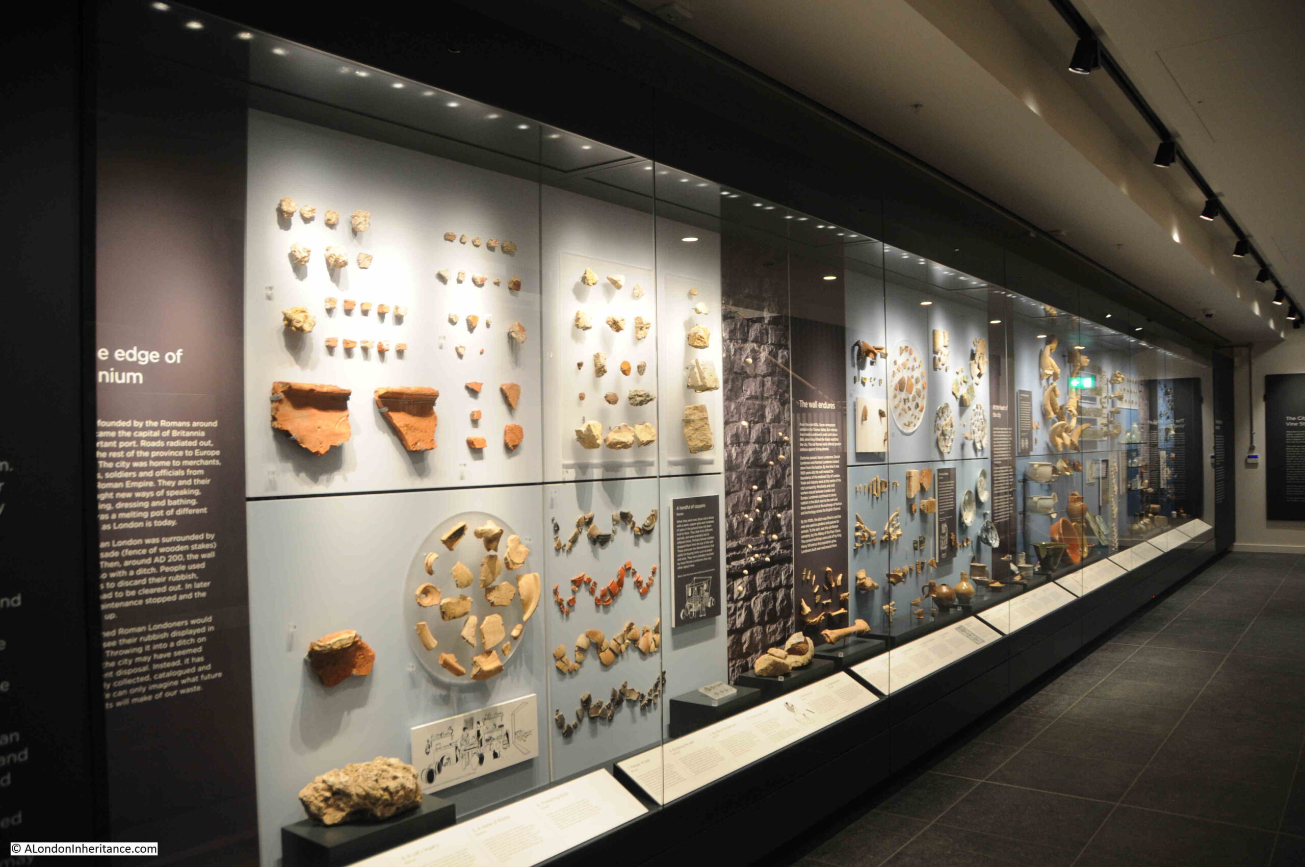
Vine Street Roman Wall

The finds represent the whole period that the wall has stood on the site. As the level of the ground increased in height, centuries of London’s rubbish, broken pottery and china, accidently lost personal items, animal bones and the waste from industrial activities have all accumulated:
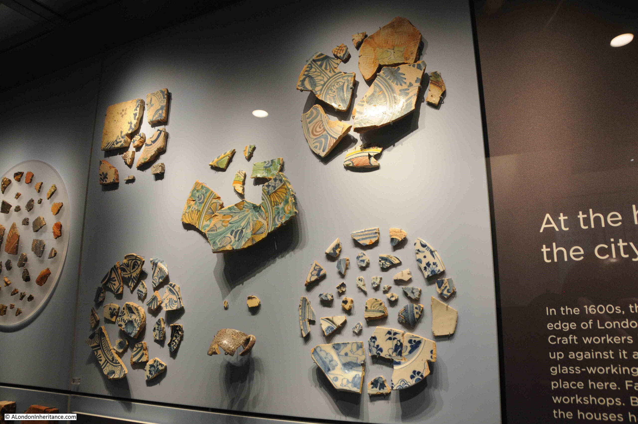
Vine Street Roman Wall

One of the finds is a bit of a mystery. It was found further to the south in 1957, during construction work in Crosswall. It appears to be a stele (an upright stone slab bearing a relief and / or an inscription, and often used as a gravestone):
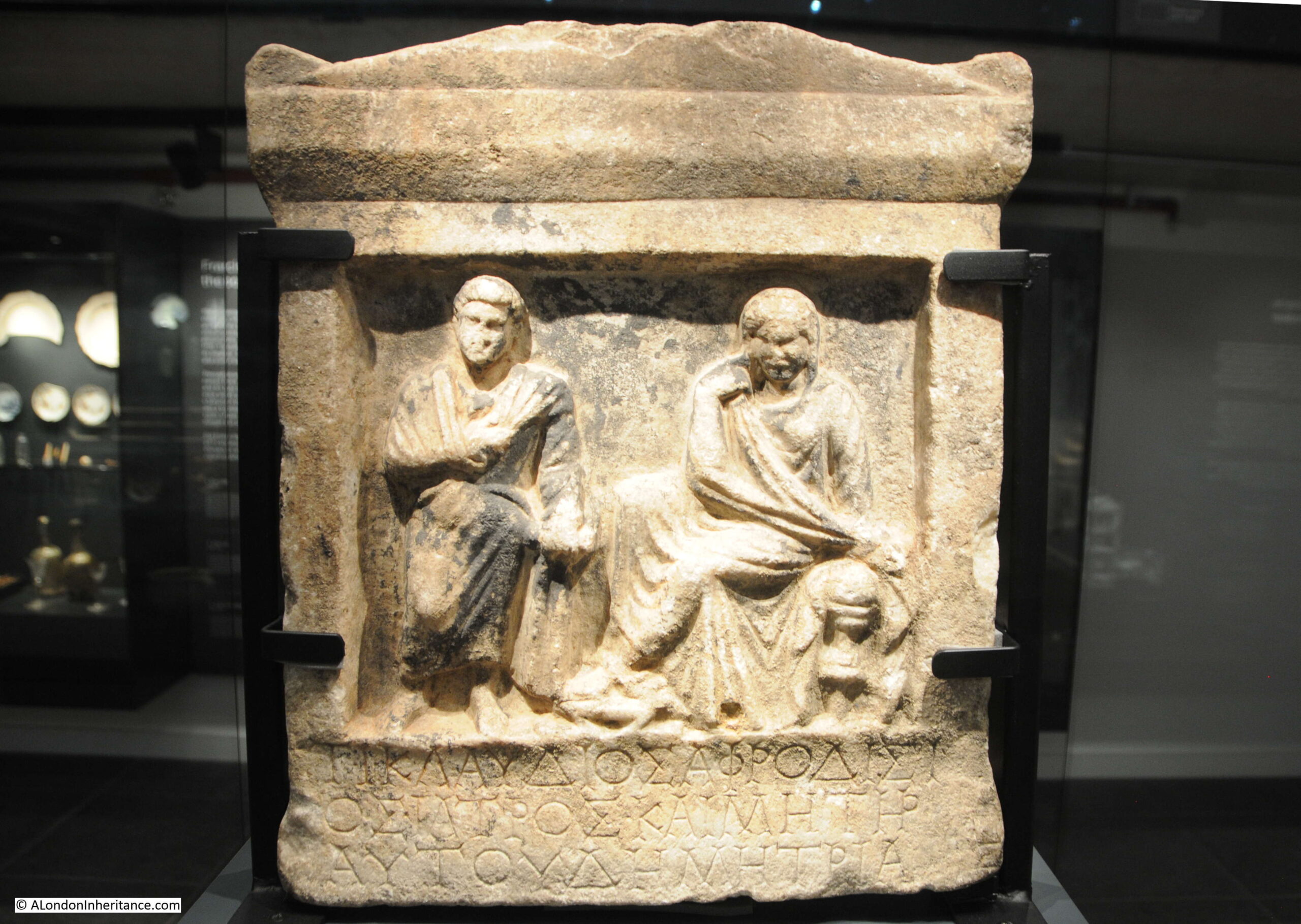
Vine Street Roman Wall

It is believed to have come from the eastern Mediterranean and dating from around 200 BC, with the inscription perhaps being added a couple of centuries later.

It is unclear how the stone came to be in the City of London, and one of the theories put forward was that the stone was brought to London many centuries later during a Grand Tour, when those rich enough and still relatively young, would embark on a tour through the major cultural and historical centers of Europe and bring back artifacts from their travels.

The Vine Street Roman wall is also very well worth a visit. A different form of presentation to the Temple of Mithras, but it shows how the wall survived by becoming part of much later buildings.

Details can be found at the website of the Vine Street Roman Wall, here.

alondoninheritance.com

The IMAX Roundabout at the end of Waterloo Bridge

Roundabouts in cities are a problem. Whilst they are built to simplify traffic flow, they take up a large amount of space, and leave a central area for which it is difficult to find a purpose due to its isolated location.

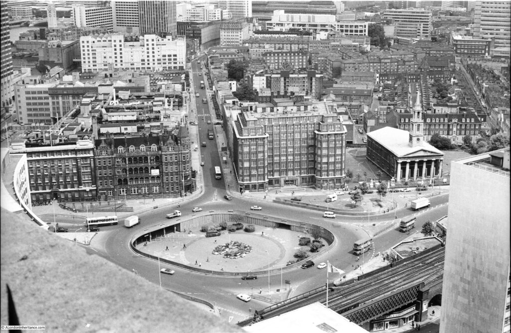
One such roundabout is at the southern end of Waterloo Bridge, where York Road, Waterloo Road, Stamford Street and the approach to Waterloo Bridge all meet. I photographed the roundabout from the Shell Centre viewing gallery in 1980:

Roundabout at the end of Waterloo Bridge

Beneath the roundabout were a large number of pedestrianised access routes to the surrounding streets and the central space provided access between these, so you could walk between any of the surrounding streets without having to cross a road.

It was always a rather bleak space. Concrete planters were scattered around the central space, and for a time in the 1980s the GLC organised what we would now call a pop-up market at lunchtimes, hoping to attract workers from the surrounding offices, although with traffic on the surrounding roundabout, it was not that pleasant and most people headed to the Jubilee Gardens or the walkway alongside the Thames.

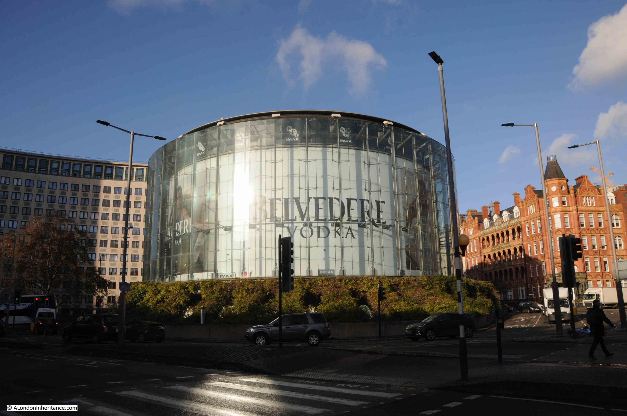
A rather innovative use for the central space was found in the late 1990s when the British Film Institute opened an IMAX Theatre in the centre of the roundabout:

IMAX Theatre at end of Waterloo Bridge

The IMAX is of circular design to fit the central space, and is surrounded by a glass wall which makes the building ideal for advertising and for displaying films that are being shown in the theatre. It is a very obvous landmark when approaching from any of the surrounding streets, and with the low sun of a December day, produces strange light reflections on the streets of the roundabout.

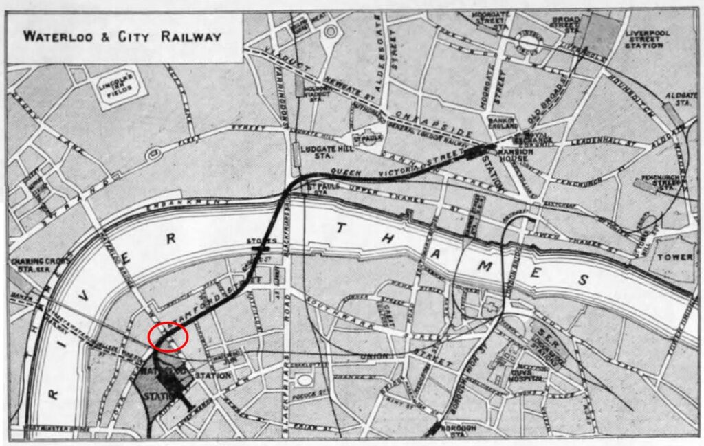
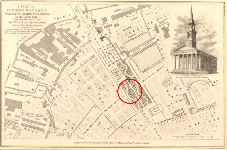
So, a very clever use of a difficult city space. One that has to overcome a number of obstacles, for example vibration and soundproofing from both the traffic on the roundabout, and the Waterloo and City line which runs just 4 metres below the theatre, which gives me an excuse to show a map of the route of the Waterloo and City line, with the location of the roundabout and IMAX marked by a red circle (Credit: The Engineer, July 26, 1895, Public domain, via Wikimedia Commons):

Old map of the Waterloo and City line

The IMAX Theatre was opened in 1999 and designed by Bryan Avery Architects. I have walked past the IMAX countless times, but what got me thinking about the use of space and the problems of inner city planning and maintenance was when I was walking alongside the roundabout in late December.

Access to the IMAX is via the steps down from the surrounding streets that also provide access between the streets without having to cross at surface level.

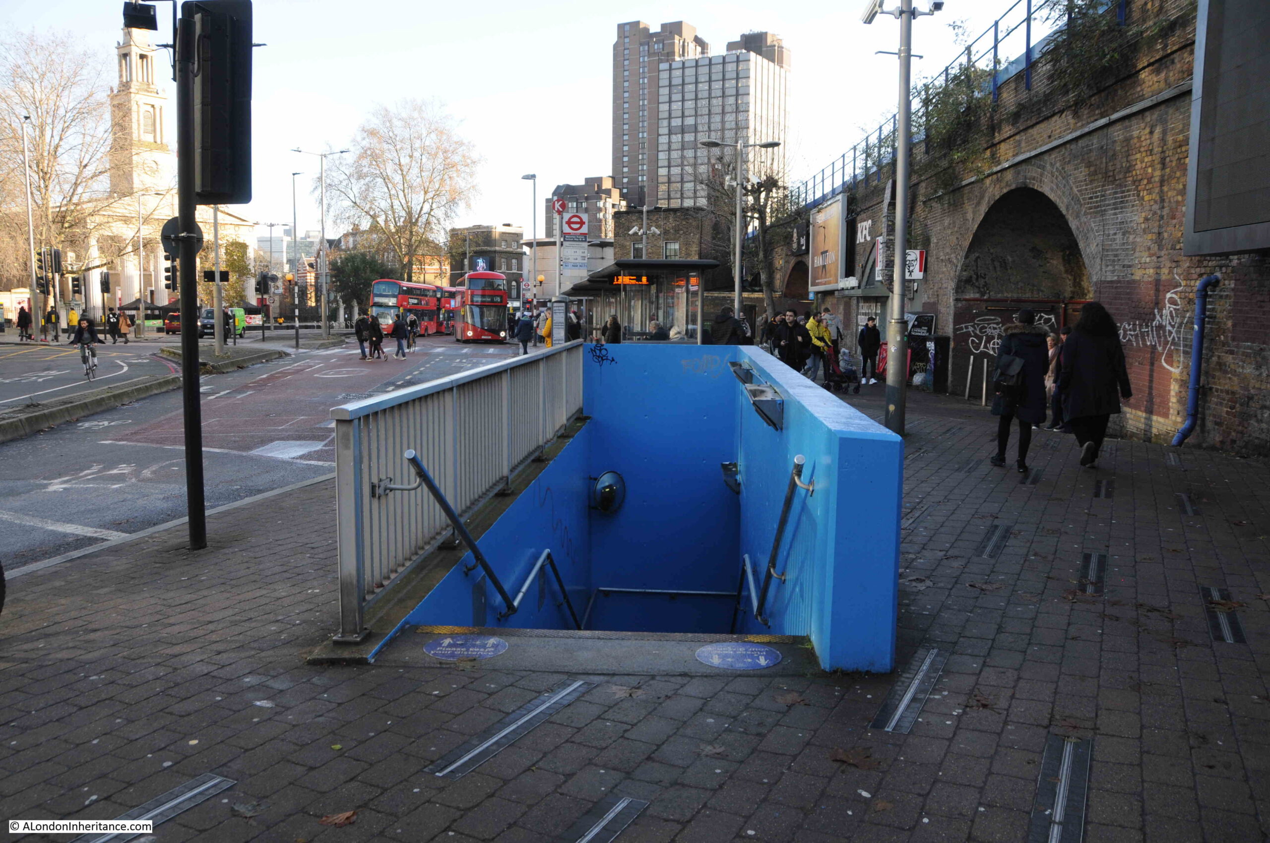
The steps down in the following photo are on the side of the roundabout between York Road and Waterloo Road. It was the start of the Christmas school holidays and I noticed a mother and child going down the stairs, then coming up, looking around, walking to another set of stairs, then back to the one in the photo. They were going to the IMAX, but there is no obvious signage and the stairs down do not look the most inviting.

Tunnel to IMAX Theatre from Waterloo

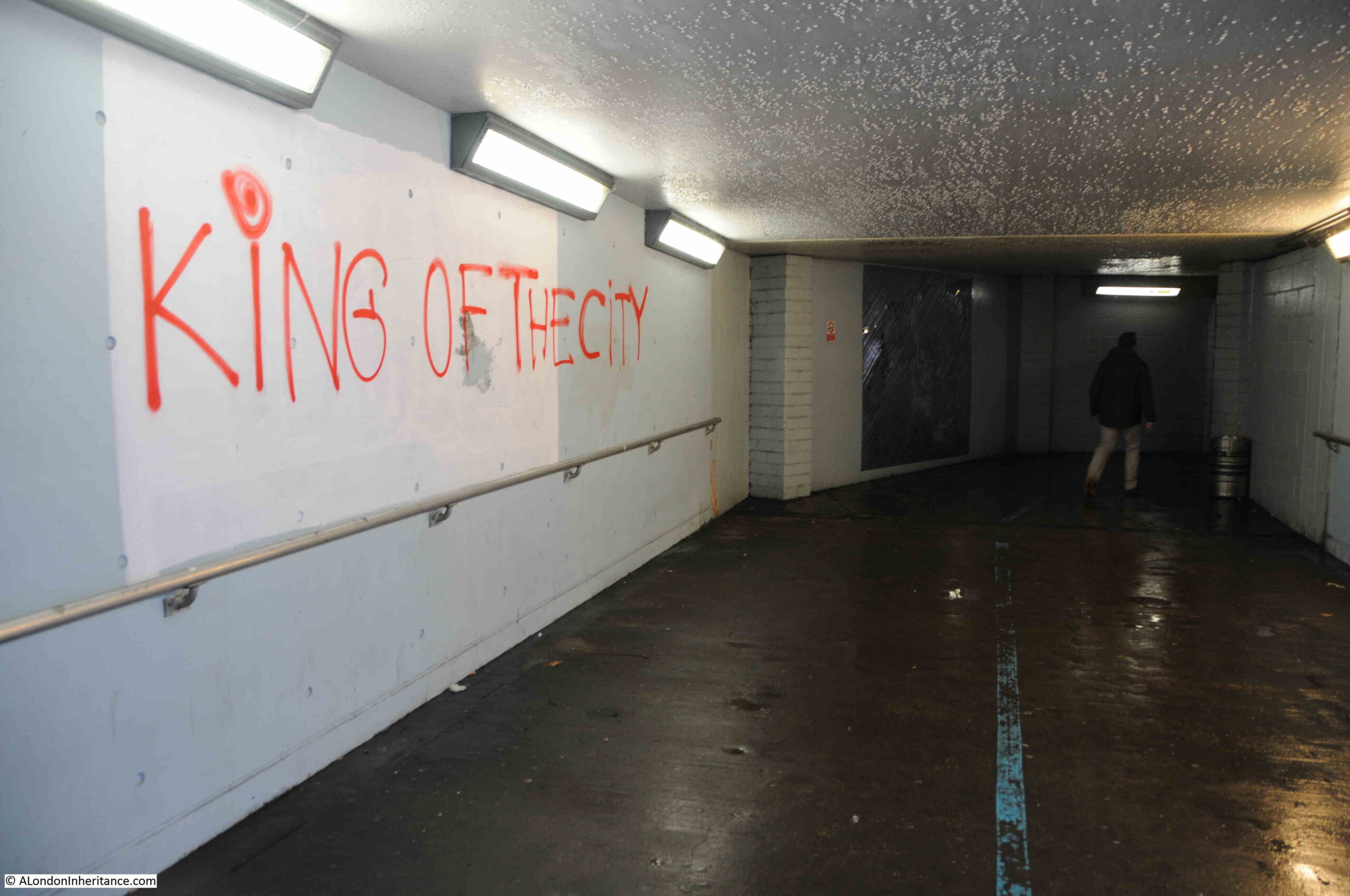
I walked down the stairs, and met the smell that is familiar to such spaces:

Tunnel under roundabout

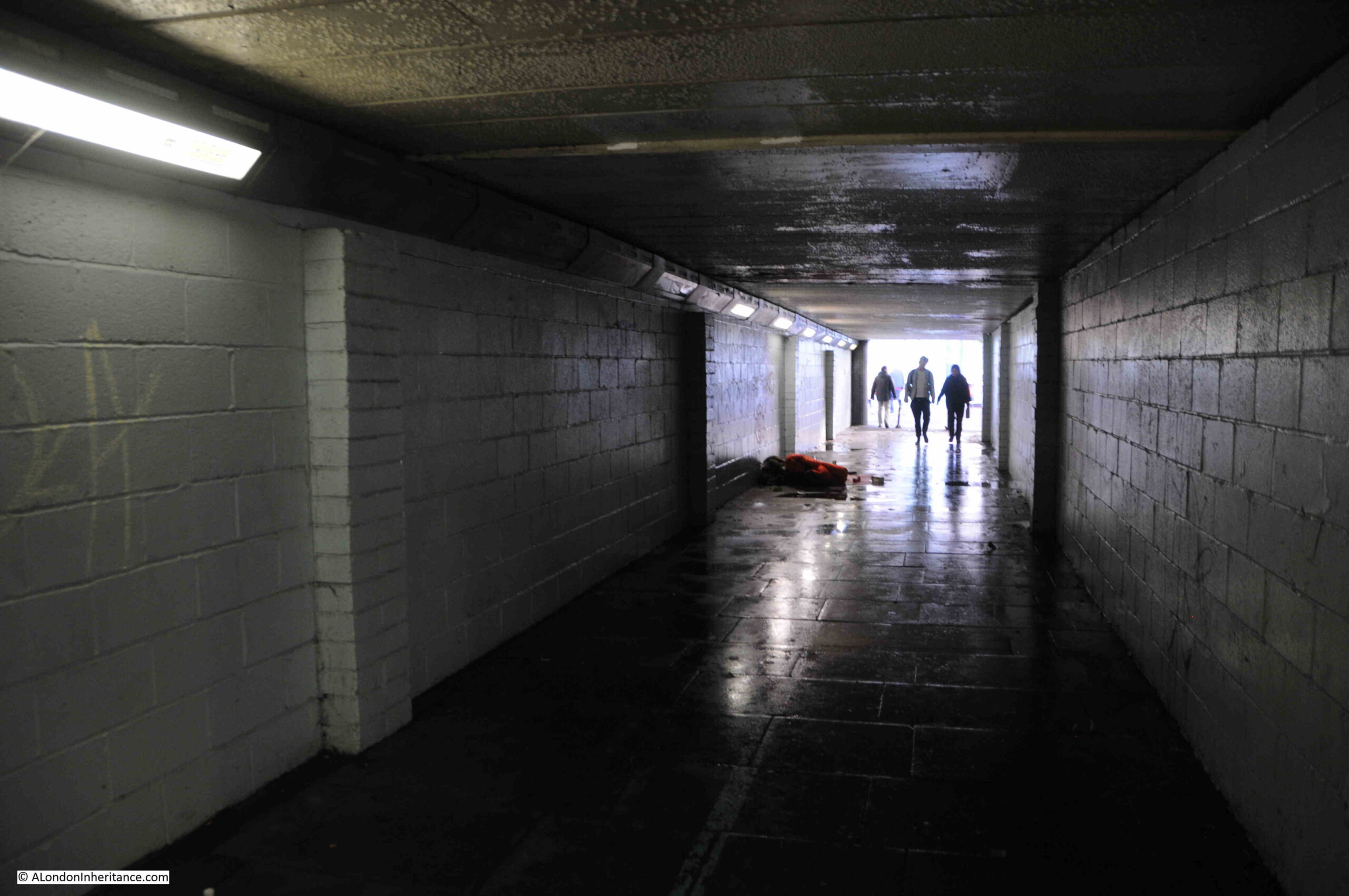
Tunnel under the roundabout leading to the central space and the IMAX:

Tunnel under roundabout

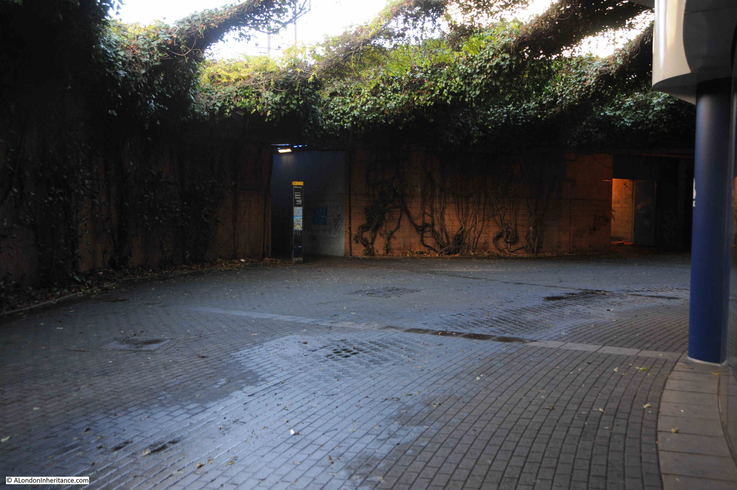
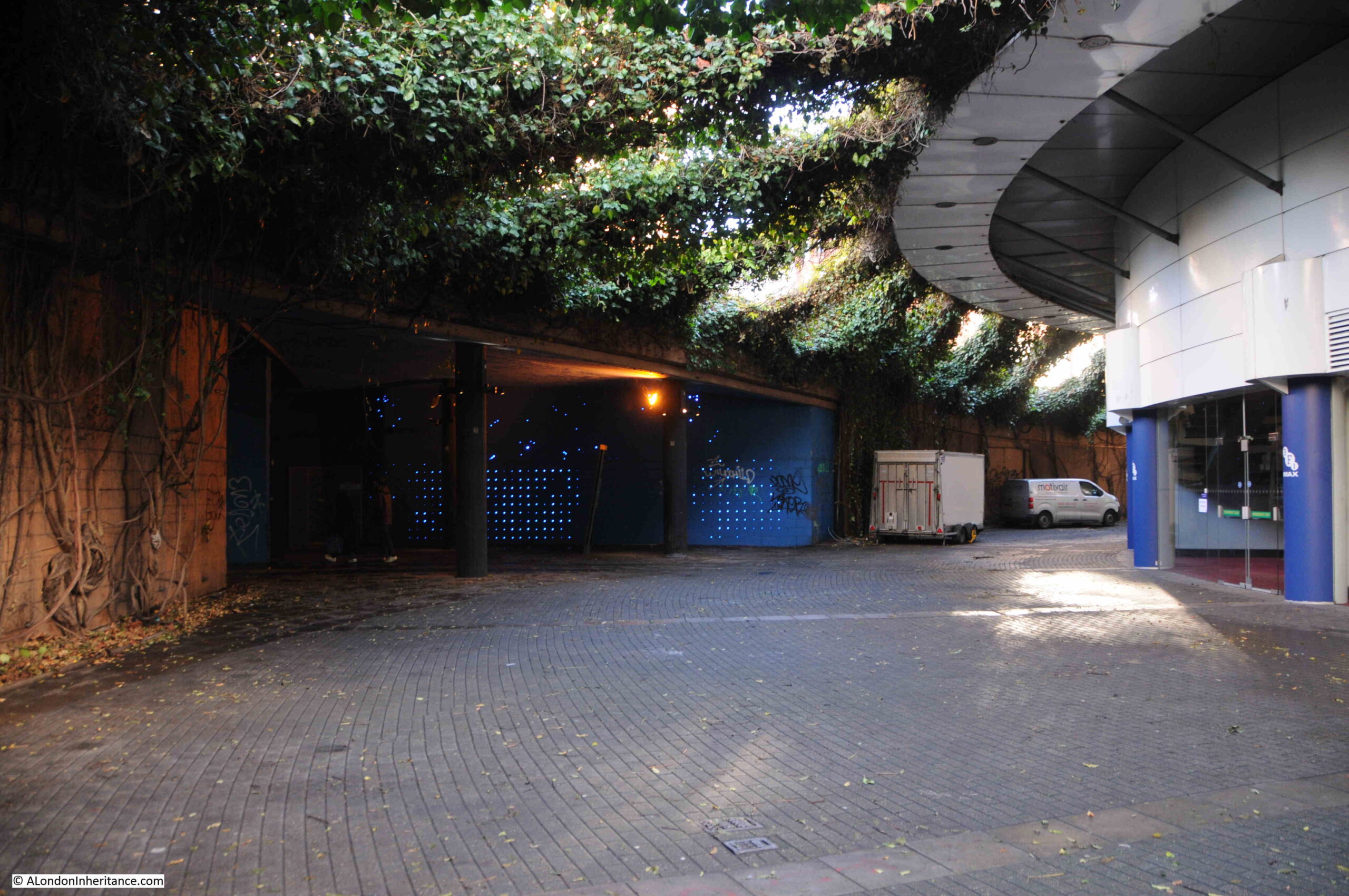
Once in the central space of the roundabout, we can see the curving wall of the IMAX and the extensive planting that creates a rather unique space:

Area around the IMAX Theatre

More than 2000 plants were originally planted, comprising of honeysuckle, jasmine, wisteria, clematis, ivy, Boston ivy and Japanese vine. An automated watering system was installed, which looks to have worked well as the plants now look very established and have grown up from the side walls, across supporting cables and up to the sides of the IMAX:

Area around the IMAX Theatre

There is a very tenuous link between the current centre of the roundabout, and an earlier use of the space, when it was occupied by Cuper’s Gardens, one of the many gardens and places of entertainment that were found on the south bank of the river in the 17th, 18th and early 19th centuries.

The following map is interesting as it shows the area in 1825, eight years after Waterloo Bridge was opened. It is titled “A Plan of Cuper’s Gardens with part of the Parish of Lambeth in the year 1746 showing also the site of the Waterloo Bridge Road and the new roads adjacent”.

The map helps define the exact location of Cuper’s Gardens as the church of St. John is also shown. The large roundabout (circled) now covers part of Cuper’s Gardens at the junction with Stamford Street:

Old map of Cuper's Gardens and Waterloo Bridge

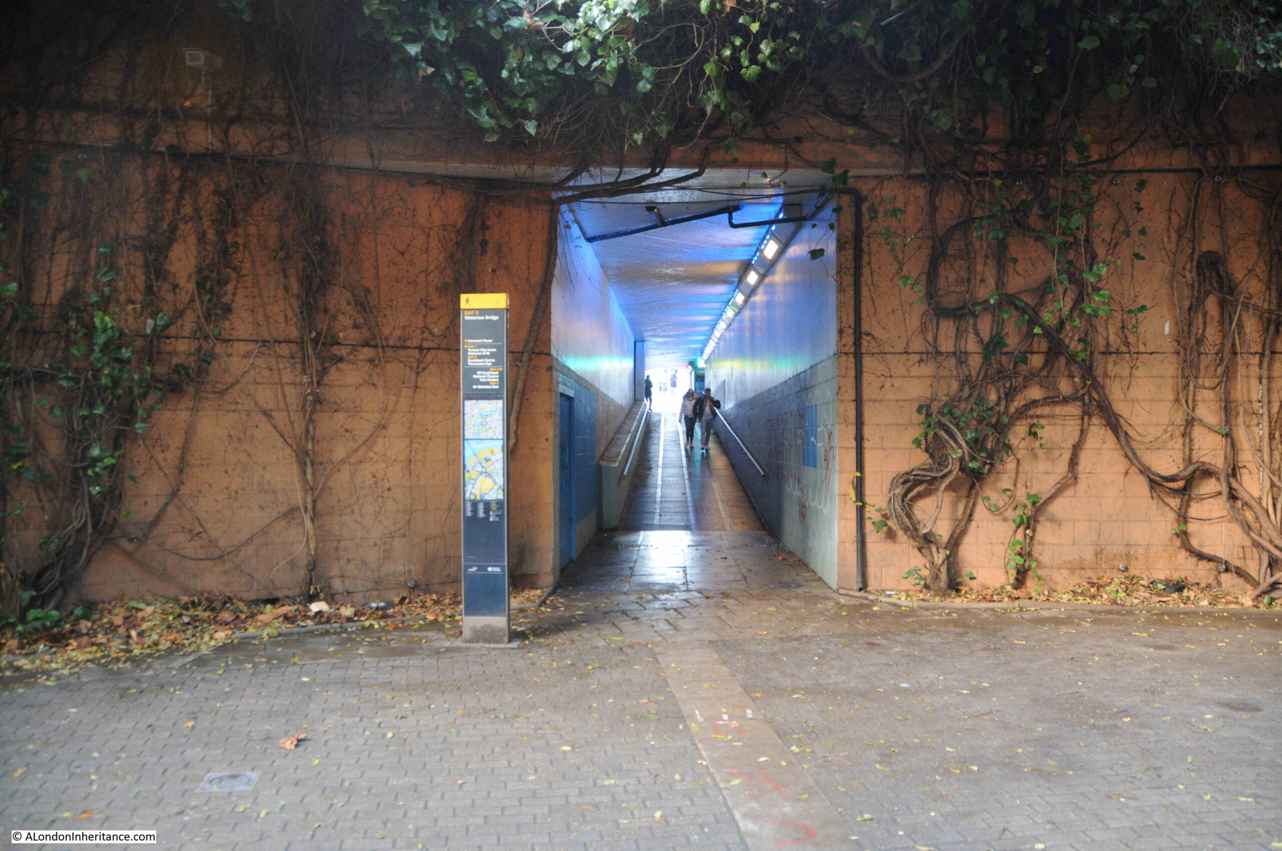
The “gardens” around the IMAX are very different today, and the whole area is rather a surreal space. The outer wall has been painted light brown, possibly to resemble the earth through which the space descends. Large, twisted trunks (which look like roots) of the presumably now over 20 years growth extend up along the walls, and the outer wall is occasionally cut through with the access tunnels to the streets above:

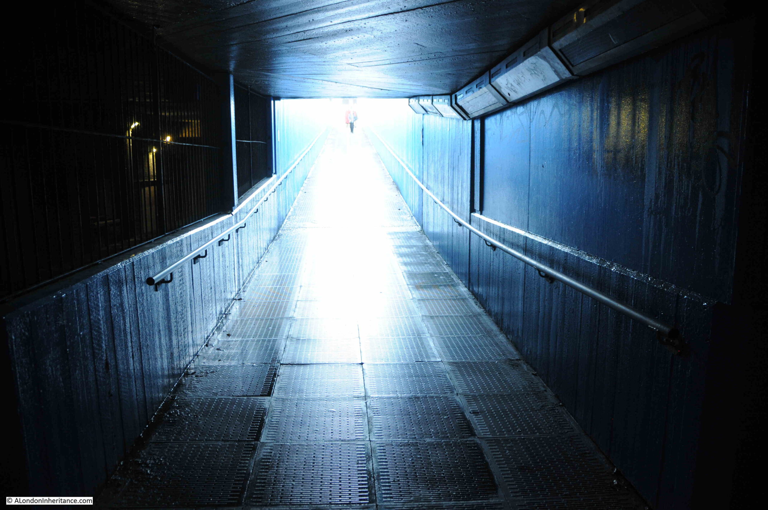
Tunnel leading up to Waterloo Bridge

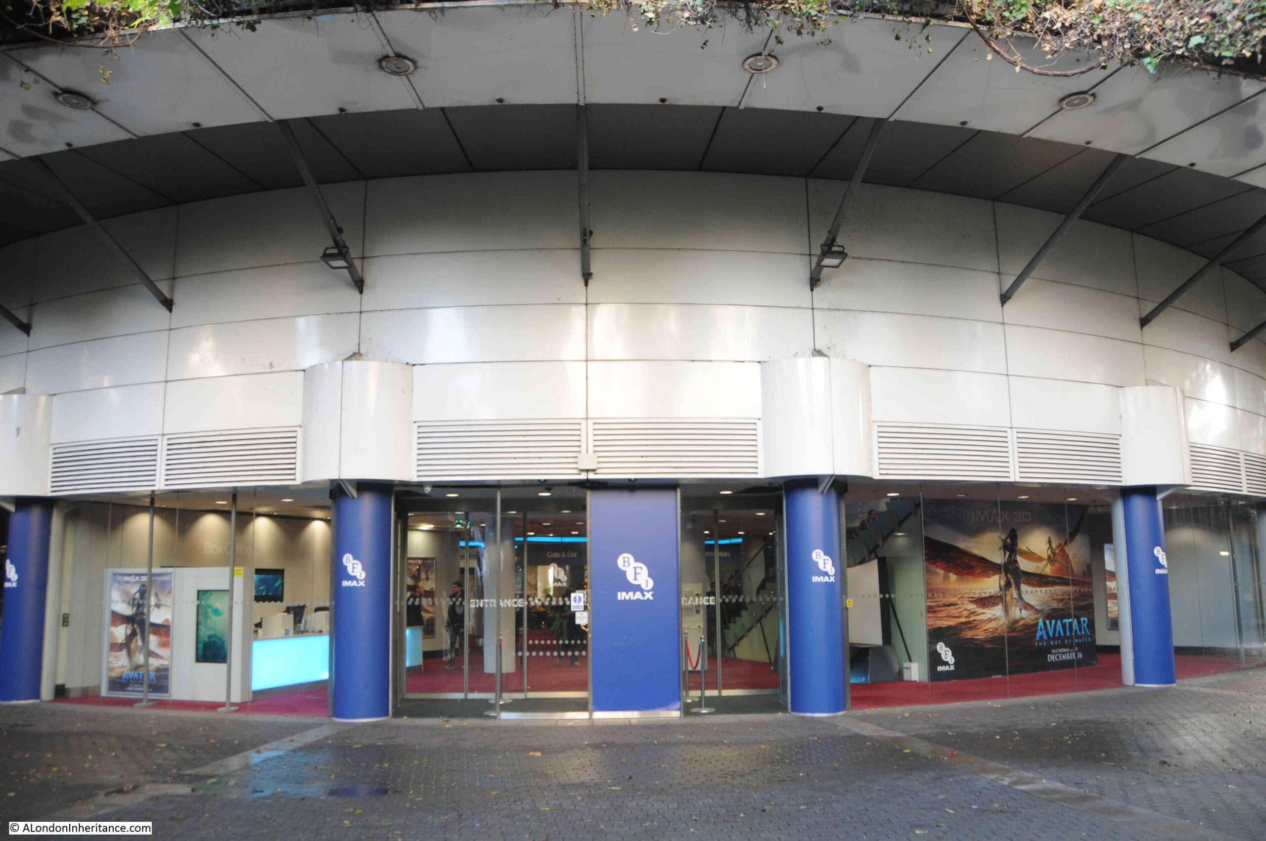
The entrance to the IMAX Theatre:

IMAX Theatre

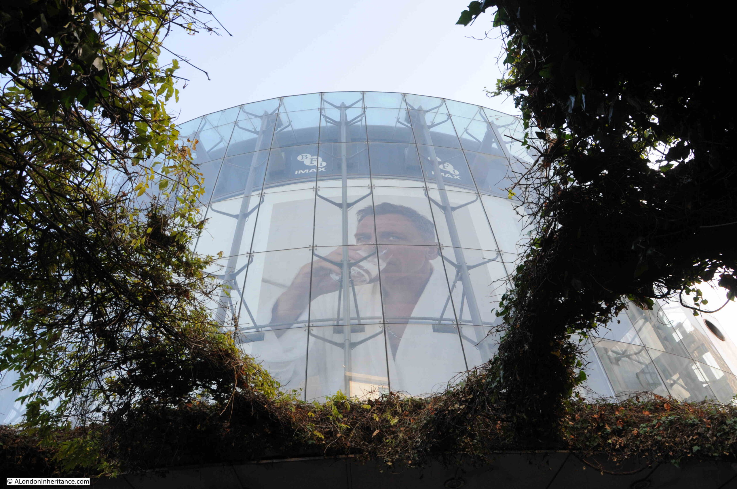
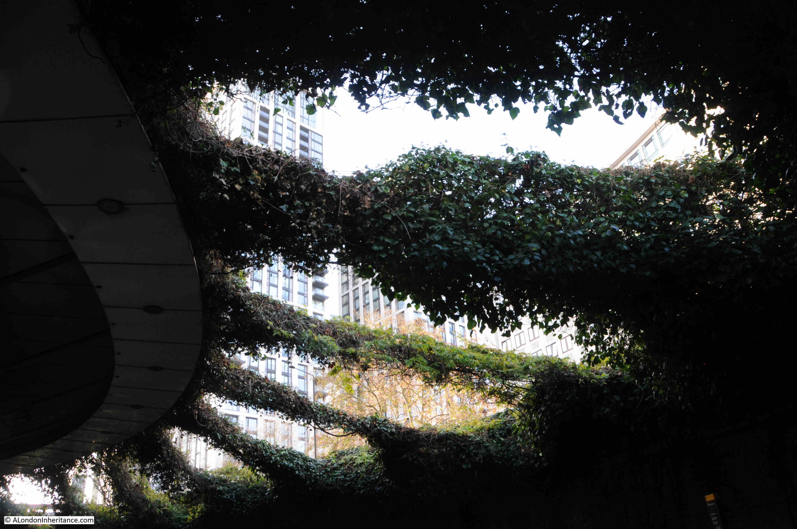
Looking up between the planting and the curved glass wall of the IMAX dominates the view:

IMAX Theatre

When the IMAX was opened, as well as the central space surrounding the theatre, the walkways and tunnels leading up to the streets were cleaned, restored and painted, with many of the walls being painted blue, and some lighting being set into the walls.

IMAX Theatre

You can see the effect that this was intended to create. The central space with substantial overhead plant growth, the surrounding earth coloured walls, covered in the trunks of the plants, with the walls being cut through by the blue painted walkways to the surrounding streets.

It all creates an intriguing and surreal space, appropriate for walks to the IMAX.

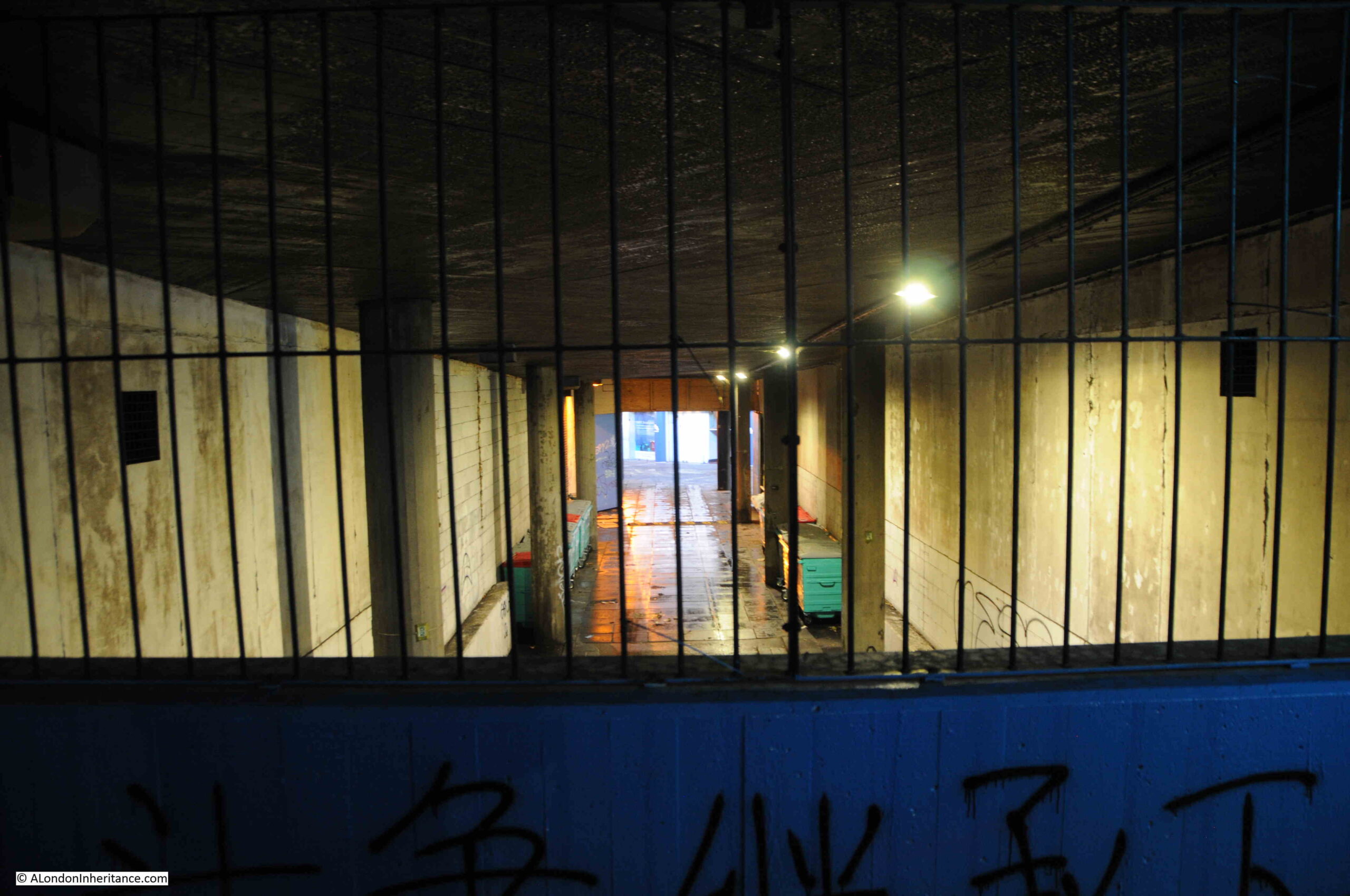
Service access tunnel and pedestrian walkway leading to Belvedere Road:

Tunnels under Waterloo Bridge

View up through the plants with the new tower blocks that have taken much of the old Shell Centre site:

View from IMAX Theatre

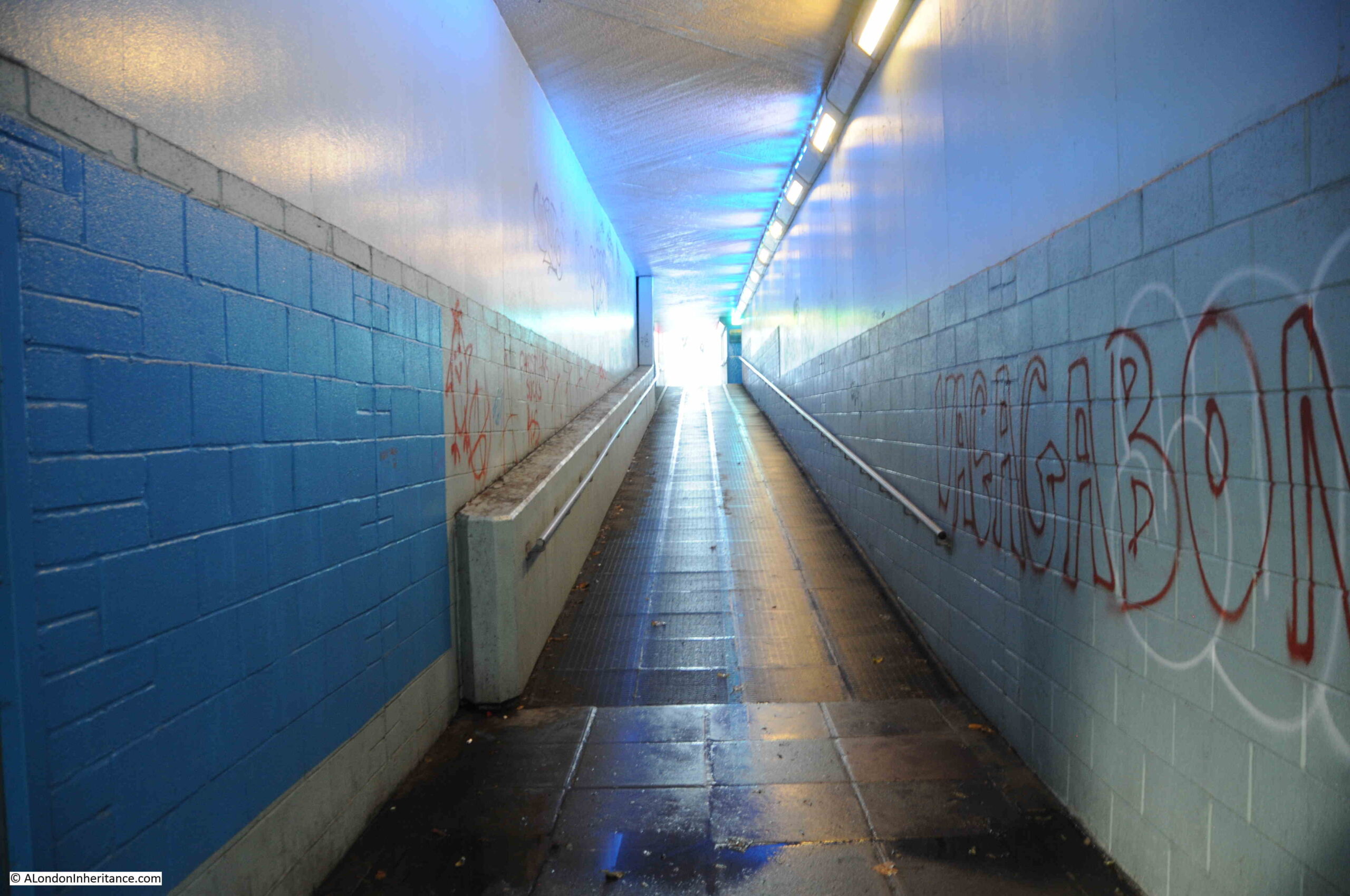
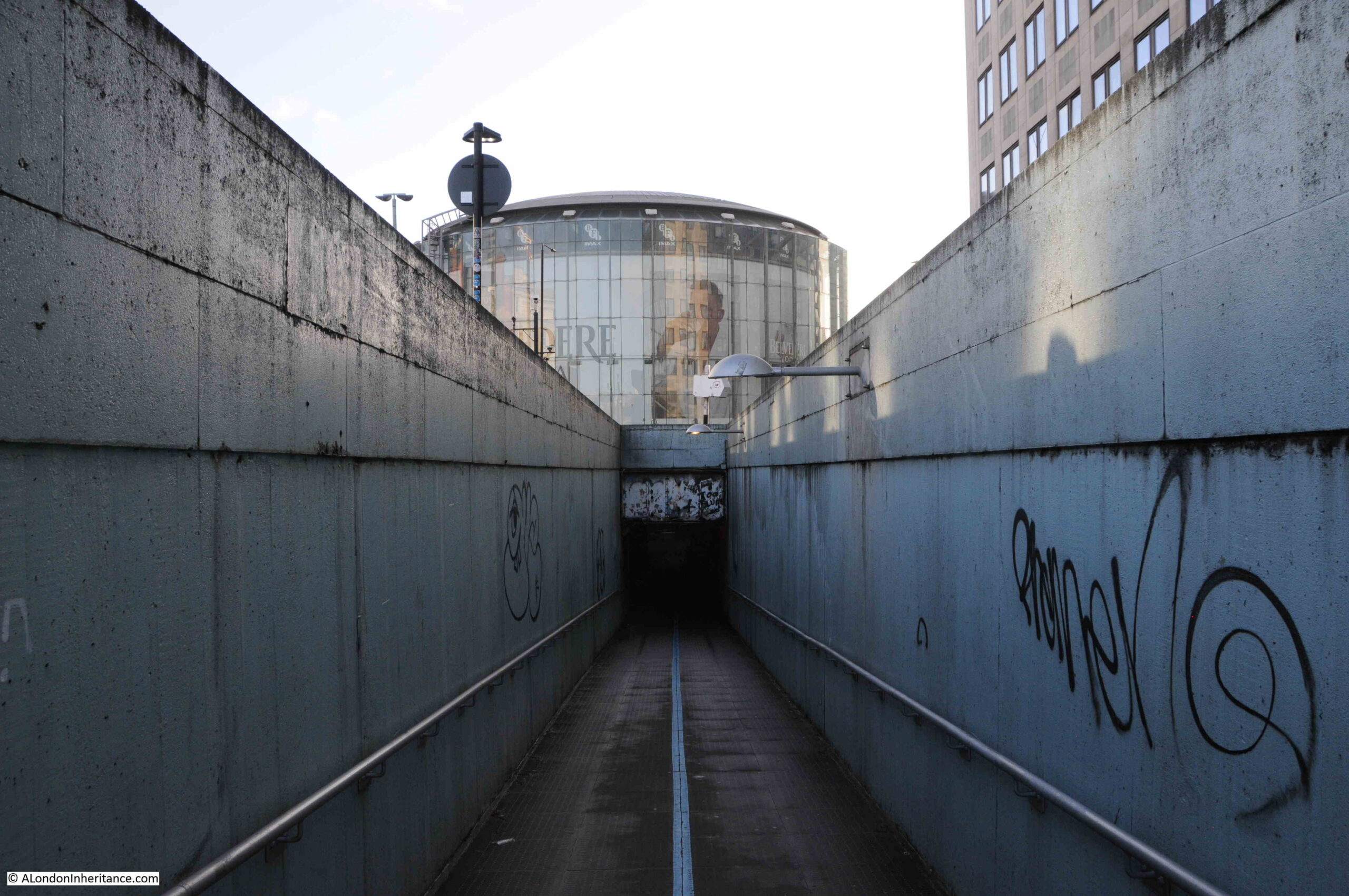
Walking up to the surrounding streets, and it is clear what was intended, and the problems that result in the walkways not being that much of an inviting route to the IMAX. The following photo shows the walkway up to the western side of Waterloo Bridge:

Access tunnel from IMAX to Waterloo Bridge

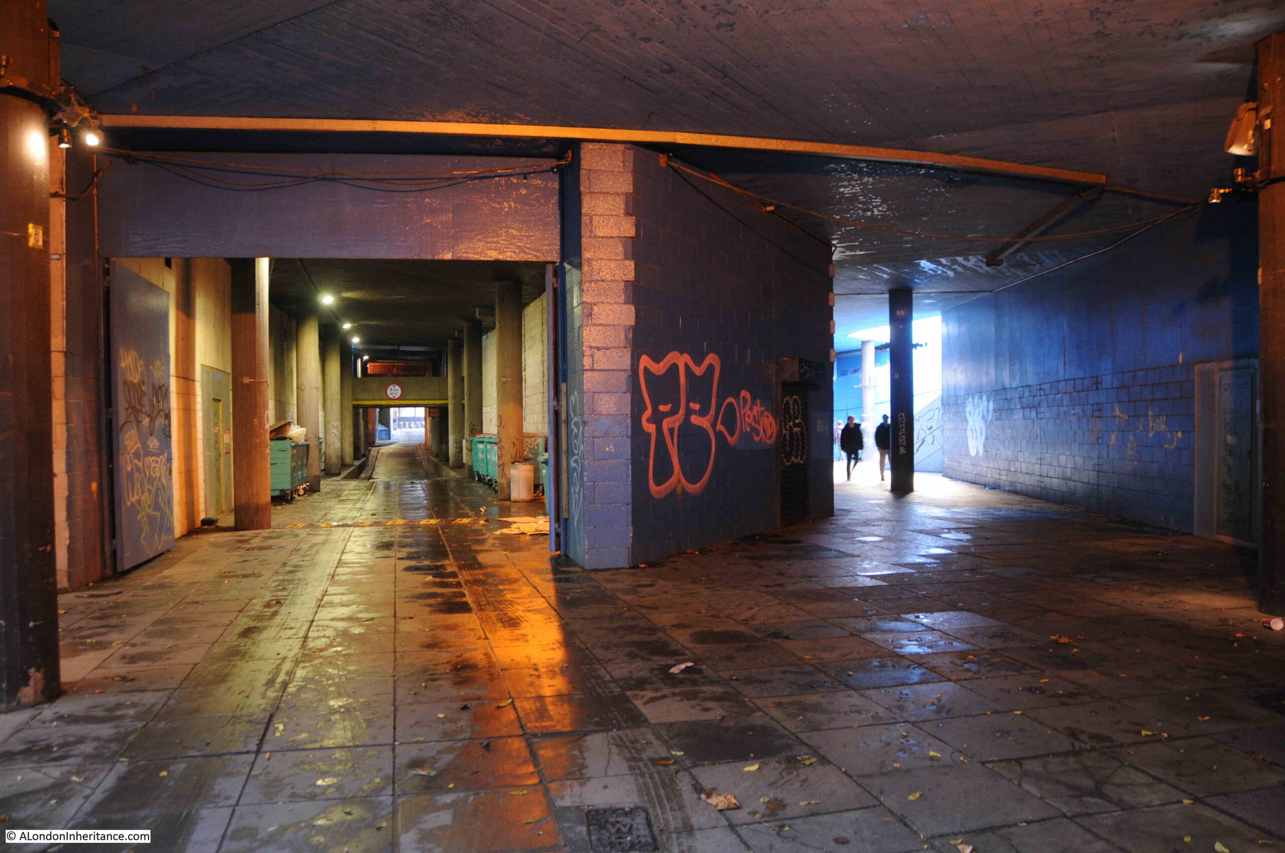
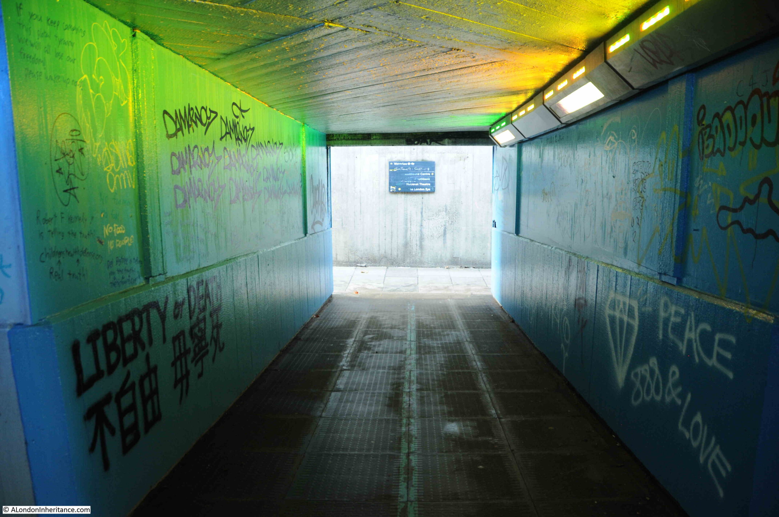
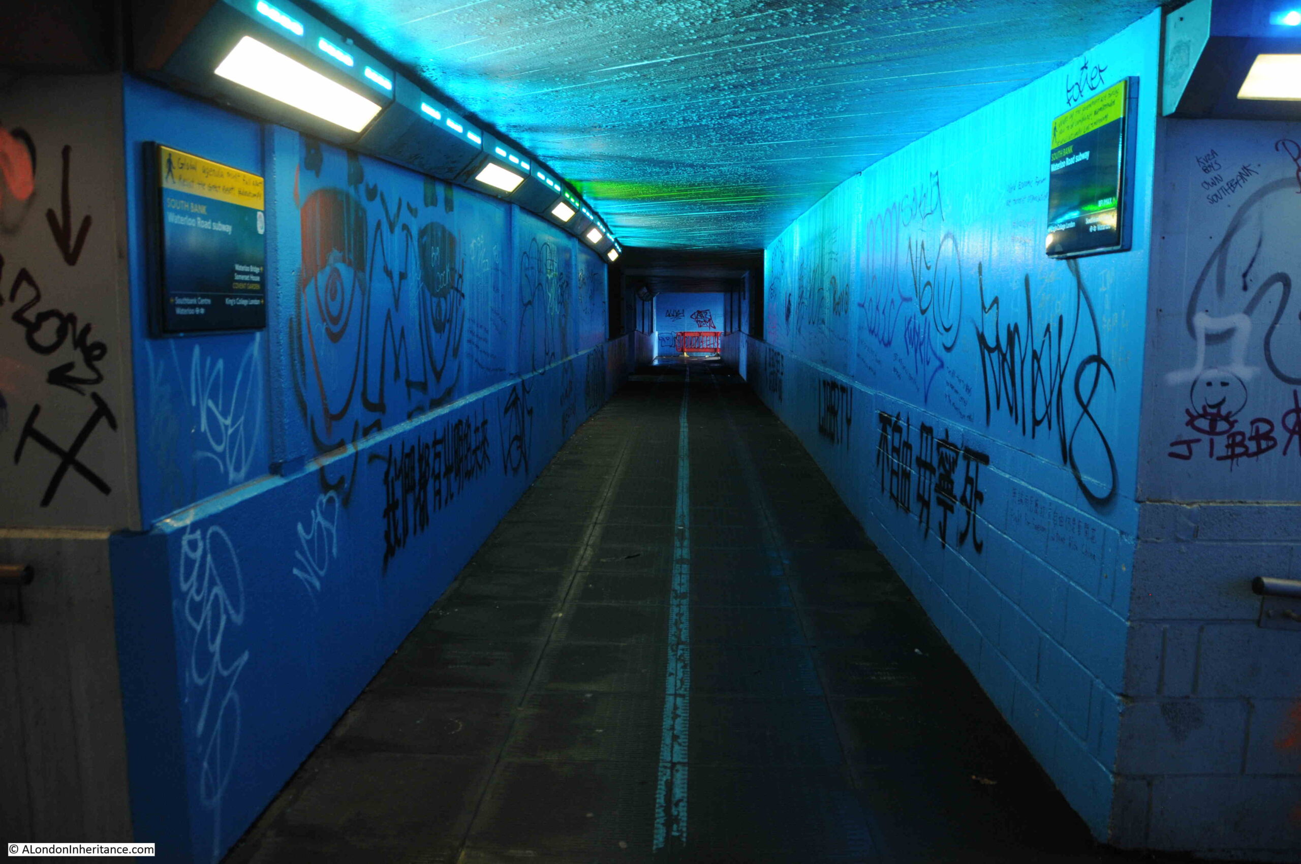
Many of the walls are covered in graffiti, including the main walkway, and the tunnels that connect the east and west walkways:

Under Waterloo Bridge

Many of these walkways and tunnels make really good subjects for photography. The blue walls, the grafitte, and the hidden destination of these tunnels adds to their mystery, however if you did not know the area, were taking children to the IMAX, and it was at night, they are not inviting, and there were very few people using them as I wandered around taking photos.

Under Waterloo bridge

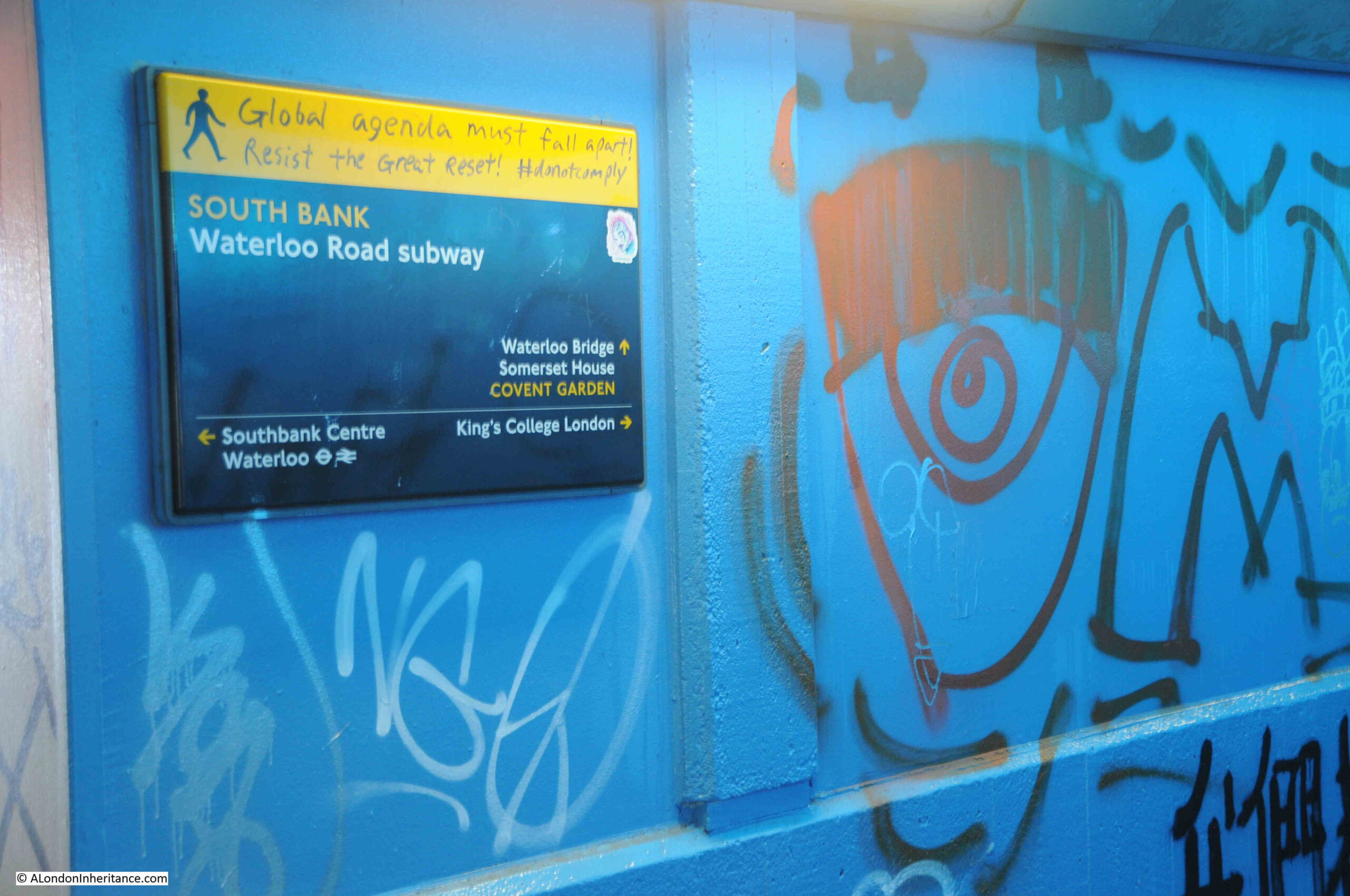
Global conspiracy theories meet South Bank direction signs:

Under Waterloo Bridge

Looking back down the walkway from the western side of Waterloo Bridge:

Underground tunnel leading up to Waterloo bridge with IMAX in background

Whilst the view of the IMAX in the above photo provides an indication of the destination of the walkway and the tunnel, it does not encourage you to walk down, there should be signs above the tunnel and better lighting in the entrance to the tunnel.

One of the walkways that crosses between the west and east sides of Waterloo Bridges crosses the service tunnel:

Under Waterloo Bridge

Walkway up to the eastern side of Waterloo Bridge:

Underground tunnel leading up to Waterloo Bridge

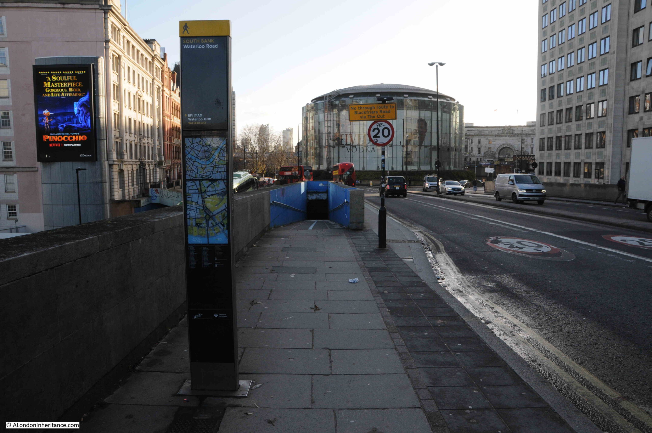
This is the view from the eastern side of Waterloo Bridge, with the IMAX in the centre of the roundabout, and the blue painted entrance to the walkway and tunnels that lead to the IMAX:

IMAX Theatre from Waterloo Bridge

The direction post to the left of the pavement does have a direction to the IMAX with an arrow pointing straight up, the implication being to head down the tunnel rather than walk on the pavement to the right. As with the other entrances, the tunnel does not offer an inviting prospect. No signage above the point where the walkway enters the tunnel and poor lighting at the entrance to the tunnel so it looks very dark and forbidding.

The Waterloo IMAX Theatre is a brilliant use of a difficult space, as well as being a building that has some technically clever ways of avoiding sound and vibrations. For example, the first floor is mounted on oil-damped spring bearings, and the walls inside the glass outer wall are 750mm thick. During construction, pile foundations were installed around the tunnels of the Waterloo and City line. A thick concrete slab was then built on top of the pilings to support the weight of the building above.

The IMAX apparently has the largest screen of any cinema in the UK and has the equipment to support normal film format as well as IMAX Digital and 3D.

A shame that whilst the intention with the tunnels and walkways is clear, and they could have provided a creative and innovative space, what appears to have been limited maintenance and care over the years has resulted in a rather poor experience when walking to the theatre at the centre.

TfL did have plans back in 2017 to transform the area and remove the roundabout, creating a surface level pedestrianised space up to the IMAX, however these plans appear to have been paused due to “the pandemic and current funding restraints”.

Given TfL’s current funding constraints, I suspect the roundabout will be there for some years to come.

More 1980 photos from the viewing gallery of Shell Centre are in this post.

alondoninheritance.com

Tunnelling the Baker Street and Waterloo Railway

A couple of week’s ago, I wrote about the construction of the Greenwich foot tunnel, based on a pamphlet published in 1902 by the Institution of Civil Engineers. The pamphlet included details of another recent tunnelling project, constructing the tunnels of the Baker Street and Waterloo Railway (known from the start as the Bakerloo line), under the Thames between Embankment and Waterloo Stations.

Parliamentary Acts of 1893 and 1896 had approved construction of the Baker Street and Waterloo Electric Railway, initially running from Dorset Square near Marylebone Station, to Waterloo Station. Further requests for extensions were approved and by 1904 the line ran from Paddington to Elephant and Castle.

The route of the Baker Street and Waterloo railway ran beneath the Baker Street Station of the Metropolitan District Railway, by Regent’s Park and Crescent Gardens into Portland Place, through Langham Place to Oxford Circus (where the tunnels pass over those of the Central Line with a clearance of only 6 inches at one point), down Regent Street to Piccadilly Circus, along Haymarket and Cockspur Street to Charing Cross, along Northumberland Avenue, then under the Thames to College Street, Vine Street and Waterloo Station.

The majority of the tunnel went through London Clay and was a relatively easy construction project, however there was a challenge where the tunnel went underneath the Thames.

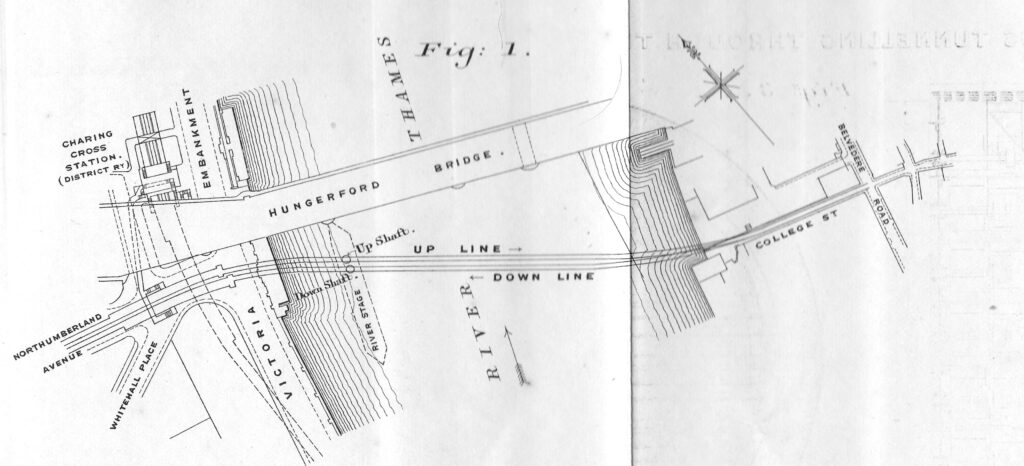
The following diagram from the pamphlet shows the route under the river, from Northumberland Avenue to College Street on the opposite side of the river. The station shown above Hungerford Bridge, labelled Charing Cross Station, is now Embankment Station.

Baker Street and Waterloo Railway

The diagram shows a “River Stage” extending south from Hungerford Bridge. This was a large platform, 50 feet wide and 370 feet long on which were built workshops, stores, steam cranes, boilers and air-compressors, staff buildings along with two shafts down to where the tunnels would be built.

The construction platform and shafts on the Thames were needed due to a strange anomaly found in the bed of the river when test boreholes were made along the route of the tunnels.

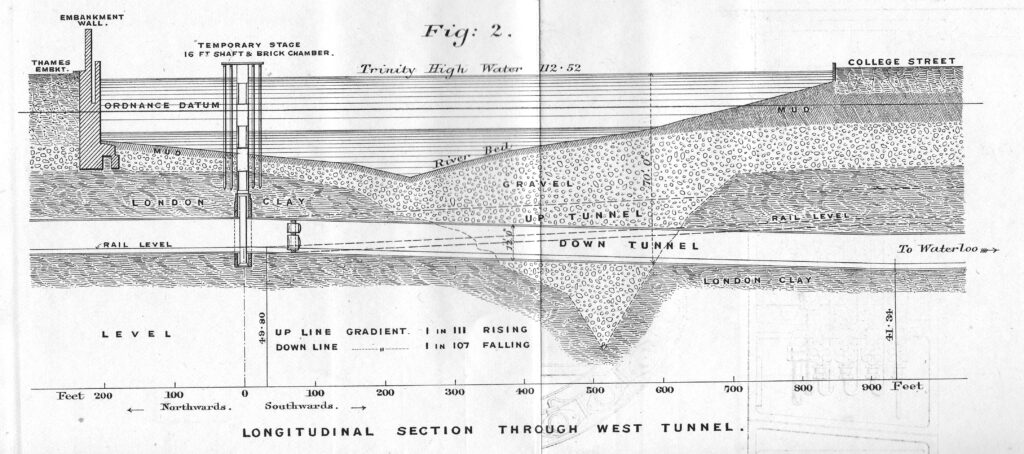
In the middle of the river there was a sudden depression in the London Clay through which the rest of the tunnel had been bored. This had filled with gravel, which was porous to water and required a different tunnelling method to the rest of the route, which would use compressed air to help keep out water as the tunnel went through the gravel.

The following diagram shows the route under the Thames of the Baker Street and Waterloo railway, the depression in the London Clay and short distance of gravel through which the tunnel would need to run.

Baker Street and Waterloo Railway

The diagram also shows the shafts sunk down to the level of the tunnels for their construction, along with the temporary work platform created on the river.

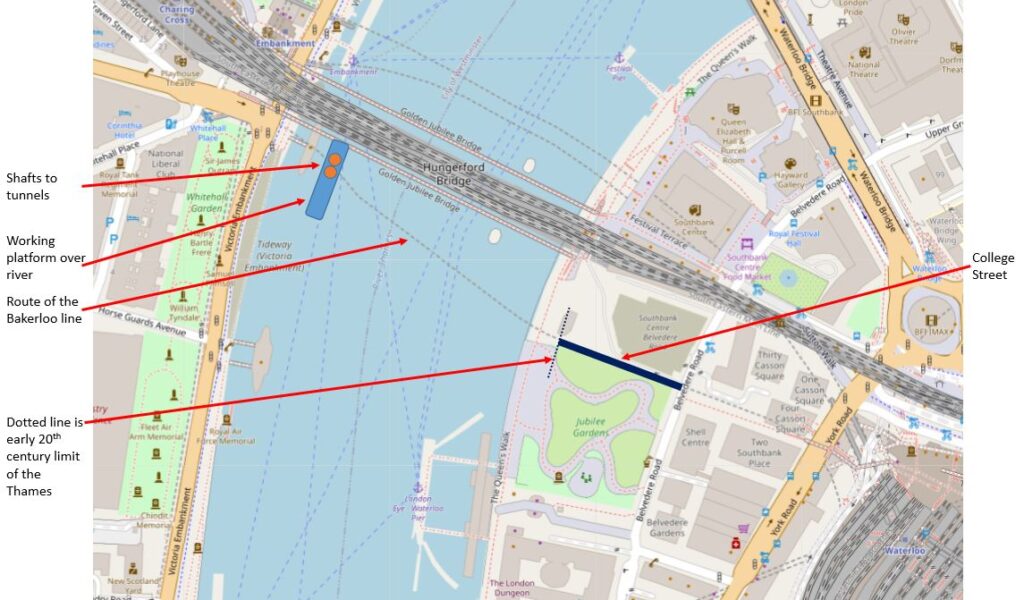
College Street on the right is now under the Jubilee Gardens.

Note also in the diagram how the depth of the two tunnels diverge as they route under the Thames, with the “up” line having a rising gradient towards Waterloo (shown as dotted lines) and the “down” tunnel having a descending gradient towards Waterloo.

The ground beneath the streets and buildings of London is generally invisible, but is just as interesting as the surface. I have written about some of the areas where the geology beneath the city has influenced the development of an area, for example, how water shaped north Clerkenwell, Bagnigge Wells, St. Chad’s Place and a Lost Well, and also when oil was found beneath the streets of Willesden.

There are many features below the surface, some as a result of ice and freezing, some as a result of water, for example when the Thames was a much wider river, and the multiple smaller rivers that ran into the Thames, and some the result of human activity.

I wondered whether the feature shown in the 1902 pamphlet was still there. I suspect we look at the Thames at low tide, and assume a uniform bed to the river as it descends from one side of the river, to rise on the opposite side.

The Port of London Authority (PLA) have a complete set of survey and navigation charts on their website, detailing the river from Teddington to Southend. They show a very different view of the Thames, a view that is essential to those on the river. The depth of water, obstructions, navigation lights, moorings etc.

A view where bridges almost disappear, with only the piers supporting the bridge shown on the chart, as these are the key features for those on the river.

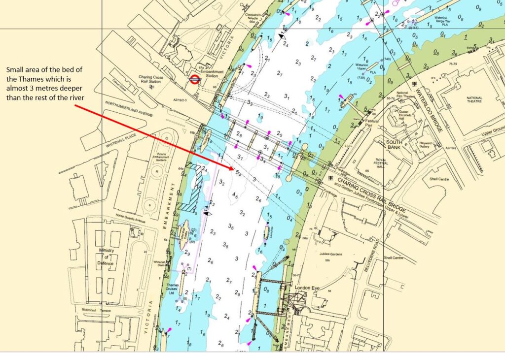
The PLA kindly gave permission for me to include an extract from the chart for Lambeth Reach in today’s post, an extract which covers the area where the tunnel for the Baker Street and Waterloo Railway was constructed.

Port of London Authority chart for Lambeth Reach

Hungerford Bridge can be seen in the centre of map, although only shown by black lines, with the piers supporting the bridge as the key feature.

The depth of the water is shown in metres (the depth is the average depth at the lower of each day’s two tides, which should show the minimum depth of water for those travelling along the river). The green areas along each side of the river are where the land is exposed at each low tide, with the height being shown (numbers underlined).

The depth of the Thames is typically between 2 and 3 metres at low tide in the central part of the river, however as can be seen just south of Hungerford Bridge (arrowed) there is a small area where the depth increases to a maximum of 5.4 metres, which is the same area as the depression in the London Clay shown in the 1902 diagram. Today’s Bakerloo line runs a short distance below the deepest area of this depression.

The PLA charts show how the depth of water gradually increases as the Thames heads towards the estuary, which is to be expected. They are some other similar features to the depression by Hungerford Bridge. For example, just off Limehouse Marina, there is a small area where the bed of the river suddenly descends from an average depth of between 6 and 7 metres, down to 11.7 metres, which is quite a depth at low tide.

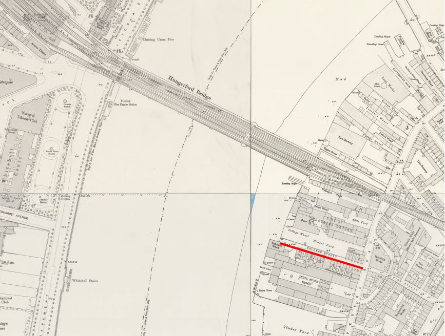
Returning to the 1902 diagram of the route of the tunnels, it shows the tunnels running under College Street on the south bank of the river. This is one of the many streets that were lost following clearance of the area for the Festival of Britain.

The 1894 Ordnance Survey map shows the location of College Street (underlined in red) in the following extract  (‘Reproduced with the permission of the National Library of Scotland“):

College Street

Interesting to compare the above map with the PLA chart. In the OS map, the priority is the land, so the river is shown as a blank stretch of water, with no defining features.

The location of College Street today, is under the northern edge of the Jubilee Gardens. The Thames has also been pushed back, with the construction of the embankment and walkway along the river for the Festival of Britain. In the following map, I have marked the location of College Street, pre-1950 edge of the river, where the shafts to the tunnels and the working platform were located, along with the route of the tunnels which today form the Bakerloo line ( © OpenStreetMap contributors).

Baker Street and Waterloo Railway

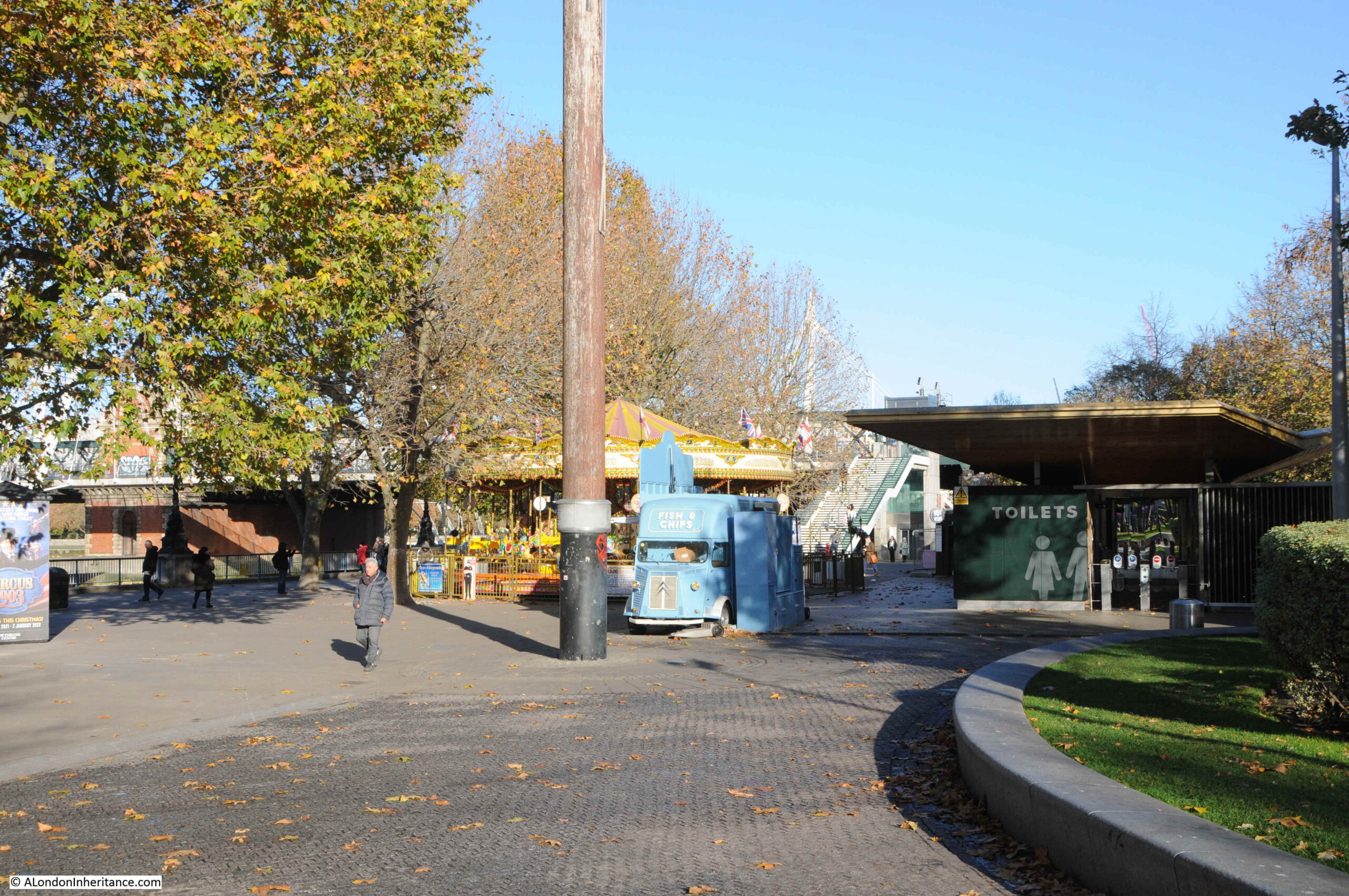
Looking at the area today, the tunnels of the Bakerloo line, run roughly under the blue van in the photo below. The edge of the grass to the right is the approximate pre-1950 boundary with the Thames.

Baker Street and Waterloo Railway

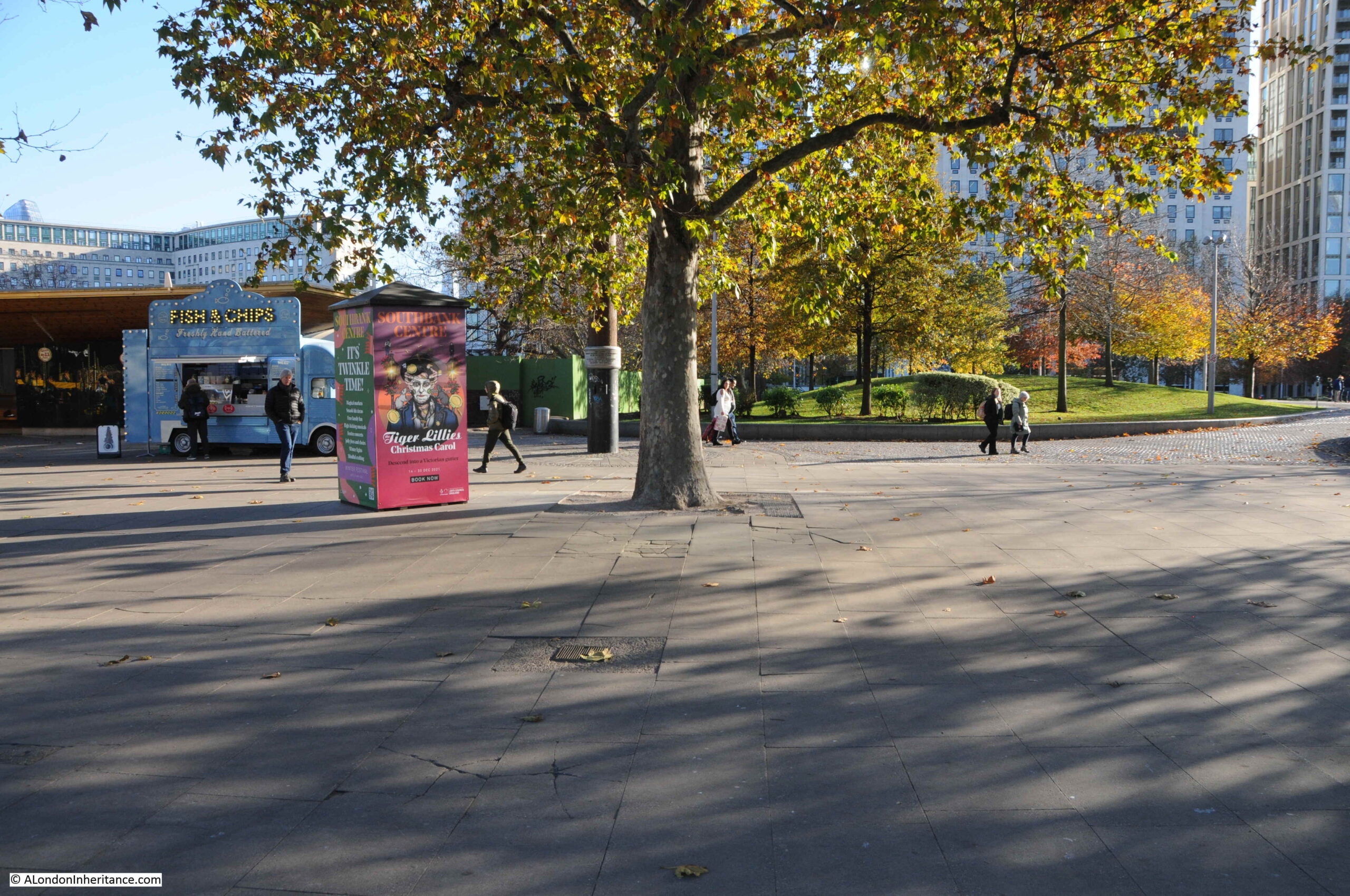
This view is looking back towards Waterloo Station from the walkway along the south bank, following the route of the Bakerloo line tunnels and College Street:

College Street

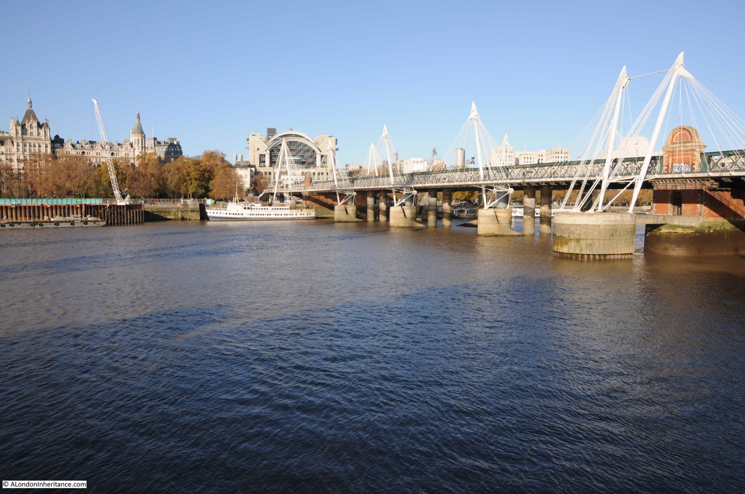
in the following view, the work platform extended from the first bridge pillars on the opposite side of the river (in front of the white boat) and extended 370 feet to the left. The depression in the London Clay is in the centre of the photo, and the Bakerloo line tunnels are running from the white ship to where I am standing to take the photo.

River Thames

One of the benefits stated in the 1902 pamphlet of the work platform in the river was that material excavated during the construction of the tunnels could be taken away by barge, saving the transport of large amounts of material through the city’s streets.

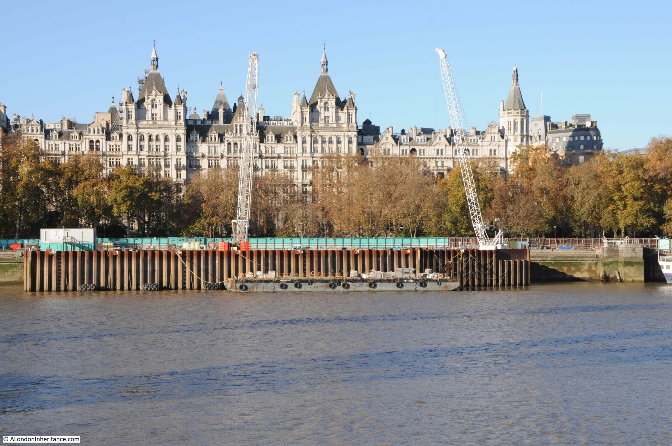
The river continues to be used for a similar purpose, with close to the route of the Bakerloo tunnels, a new construction site on the edge of the river for the Thames Tideway Tunnel or the Super Sewer, being dug at a much greater depth to the Bakerloo line tunnels, but with the same need to understand the geology through which the tunnel will be bored beneath London, and to transport materials via the river.

Thames Tideway Tunnel

There is a superb aerial view on Google Maps of the above Tideway Tunnel construction site showing the shaft down to the tunnel, which can be found on this link.

The two tunnels of the Bakerloo are each 12 feet in internal diameter, and were located in the gravel bed at a distance of 23 feet apart from the centre of each tunnel. As the tunnels approach the south bank, they move closer and the east bound tunnel will be running vertically over the west tunnel along the old route of College Street. This was done to keep the tunnels within the limits of the street.

Presumably this was done to avoid any damage to the buildings on either side of the street, or to create problems with later construction on the street, where deep cellars may have been built.

To get from College Street to Waterloo underground station, the tunnel crossed Belvedere Road and then routed along Vine Street. This street was also lost during clearance for the Festival of Britain, and in the late 1950s, the Shell Centre complex was built over the site of the street (only the tower block still remains).

I worked in the building during the 1980s, and fortunately working in what would today be called IT (lots of network, radio and telephone cabling), was able to access many of the tunnels built as part of the complex. There were two tunnels between the upstream (with the tower block) and downstream buildings of Shell Centre (on the opposite side of the railway viaduct to Hungerford Bridge). One of these tunnels was for pedestrians, and the other was a service tunnel.

The service tunnel had a raised section which went over the upper tunnel of the Bakerloo line, and it was possible to hear trains rumbling through the tunnels below.

To start construction of the Baker Street and Waterloo railway tunnels, two shafts of cast iron, 16 feet in internal diameter, were sunk from the work platform on the Thames. They reached down 50 feet. I like to assume these cast iron shafts are still below the surface, filled in, as probably too difficult and expensive to remove.

From a chamber at the bottom of the shaft, tunnels were started heading in both directions, with special attention paid to the tunnels under the Thames due to the gravel. The gravel was waterlogged, and at high tide, the combination of river and waterlogged gravel gave a head of 70 feet which created a considerable pressure of water through which the tunnel had to be driven.

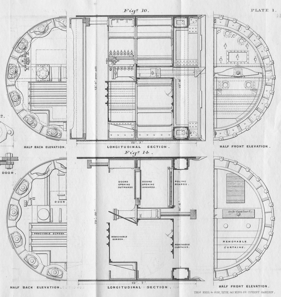
A special shield was constructed, weighing 29.5 tons and with an outer steel cylinder of 13 feet in diameter. The shield included 14 hydraulic rams, each 6 inches in diameter, to push the shield forward as the gravel in front of the shield was excavated.

The following diagrams show some of the detail of the shield’s construction, including the hydraulic rams, their controls and the pipes feeding the rams, along with elevations of sections of the shield. Each hydraulic ram could be operated independently

Baker Street and Waterloo Railway

Specially constructed iron rings were designed for the tunnel wall under the river. Each ring was 18 inches wide, and constructed of seven segments. Initially, the joints between the rings were machined to give a smooth fit between rings where bolts were inserted to join the two, however this design was soon revised with rough surfaces on the joints, which were then packed with creosoted pine wood (figures 7 and 9 below).

Baker Street and Waterloo Railway

Gaps were grouted using a specially designed grouting machine (figure 10 above), which applied the grout at pressure, through special grouting holes, to help make the rings water tight.

The first part of the tunnel was through London Clay, however as the tunnel approached the centre of the Thames, it hit the water bearing gravel shown in the diagram earlier in the post. This required a change in tunneling method.

Compressed air was now used to keep the tunnel pressure at a level slightly higher than the pressure of the water through which the tunnel was being bored. This prevented water entering the tunnel, but required adjusted working conditions for the workers, with shifts reducing from 12 to 8 hour shifts.

Air pressure was also adjusted as the tide above rose and fell as the pressure of the column of water above the tunnel through the gravel and the river changed.

As the air pressure in the tunnel was higher than the water column, air would escape from the tunnel, up through the gravel, and could be seen by those on the side of the river as water spouts, with the position of the spouts changing as the tunnel progressed across the river.

The configuration of the shield needed to change as the shield approached and entered the gravel. The following drawings show the shield as it approached and then went through the gravel (called ballast in the diagrams).

Baker Street and Waterloo Railway

Work on the first tunnel commenced on the 19th March 1900. it had taken the previous January and February to construct the shield at the bottom of the shaft. On the 2nd of April, work was stopped to allow the construction of an 8 foot thick bulkhead brick wall in the tunnel. This would form the airlock to the section of the tunnel through the gravel where compressed air would be used.

Tunneling restarted on the 2nd of May and on the 6th of June the shield entered the gravel, and on the 15th July, the tunnel was fully within the gravel.

During the period of tunneling through the gravel, there were a few “blowouts” where water entered the space behind the shield. The design of the shield allowed time for the men working to escape, and provided a means of re-entering sections, and continuing work.

On the 27th September, the tunnel re-entered London Clay, with the last of the gravel seen on the 6th October 1900.

Tests were then carried out by removing the pumped air pressure to check for leaks, repairs carried out and compressed air was ended on the 27th October, with the airlock being demolished in November 1900.

The second tunnel was constructed in 1901, with the majority of the same workers, and using many of the lessons learnt on the first tunnel. This second tunnel was completed separately as the shield from the first tunnel was reused.

There were no deaths during construction, two “illnesses” due to working in compressed air, neither of which appear to have been serious. Workers were provided with hot coffee, clean work clothes, and a place to change before and after work. A doctor was assigned to the project to monitor those working in the part of the tunnels with compressed air.

Figure 11 at the top of the following diagrams highlights the method of tunneling in loose, water-bearing gravel:

Baker Street and Waterloo Railway

The Baker Street and Waterloo Railway commenced services in 1906, from Baker Street to Elephant and Castle. The Middlesex & Surrey Express on March the 9th, 1906 provided a description of the new railway:

“The Bakerloo, London’s new tube railway, running from Baker-street to Kennington-road, will be opened tomorrow. There are intermediate stations at Waterloo, Embankment, Trafalgar-square, Piccadilly Circus, Oxford Circus and Regent’s Park, and a novelty about the new stations is that they are each treated in a separate colour scheme.

A uniform fare of twopence for the whole or any distance is to be charged, and trains will run at frequent intervals from half-past five in the morning until twelve thirty at night. The cars are of the usual type, well lighted, and with good, if not excessive provision made for ‘strap-hangers’ and one can imagine a scramble for straps taking place during the busiest hours. Collisions are rendered practically impossible for a most ingenious system, of automatic signaling has been adopted. Should, however, there be a prolonged breakdown, passengers will be able to leave the trains as a lighted footway has been provided between each stopping place along the whole length of the line.

The booking halls at the various stations are almost palatial in their design, and a feature of the lift accommodation is the use of compressed air in the rapid opening and shutting of the gates. All the wood used in construction has been rendered fire resisting”.

What is not mentioned in any of the news reports covering the opening of the Bakerloo is the tunnel under the river, and the challenges that were overcome in building two rail tunnels through water logged gravel under the Thames.

There was speculation at the time that the depression in the clay was caused by dredging for an earlier tunneling project for the Whitehall and Waterloo Railway.

This was a scheme to build a pneumatic railway in an iron tube under the river, the tube being sunk into the river bed rather than bored. The Railway News on the 20th of May, 1865, provided a description of project;

“THE WHITEHALL AND WATERLOO RAILWAY. Arrangements have now been completed which will admit of the commencement of works of this proposed railway immediately on the necessary Parliamentary powers being obtained. The bill has passed the Commons, it is now unopposed in the Lords and in a few days it may be expected to receive the Royal assent.

The railway is to be worked on the pneumatic principle, and is to be carried under the River Thames from Scotland-yard to the Waterloo Station of the London and South Western. The work must, of course, be finished before the wall of the Thames Embankment on the north side is built up, hence the necessity of pushing forward the preliminary arrangements as quickly as possible.

The railway will be formed by an iron tube, twelve feet in diameter, sunk into the bed of the river and supported in piers – a bridge, in fact, built in, not over the waters. the iron tubes will be made by Messrs. Samuda, and the laying of the tube and the other works will be undertaken by Messrs. Brassey and Co. The principle upon which the line will be worked will be much the same as that adopted on the experimental railway in the grounds of the Crystal Palace. The machinery will be on the Surrey side at the York-road Station.

The whole of the works will be completed in twelve months from the date of commencement. The cost of the undertaking will be about £130,000. The total weight of iron in the tube will be about 5,000 tons, and it will be sunk in four separate sections.”

The project soon ran into financial difficulties, the proposed timescale and costs for the project were hopelessly optimistic. In February 1868, papers were reporting that “The Whitehall and Waterloo Railway is at a complete standstill, and the directors advise the abandonment of the concern, unless, as they say, something turns up between this and the spring. They, of course, hope the South Western will help them in their difficulty, but one would think nothing could be farther from the thoughts of the directors of this company.”

In 1871, the company formed to build the Whitehall and Waterloo Railway was wound up.

The route of this earlier railway did follow much the same route as the later Baker Street and Waterloo Railway, and some parts of the iron tube were found during excavation for the construction of the Shell Centre complex, however I am not sure whether the depression in the London Clay was caused by dredging for this abandoned project.

The shape looks natural, the plan was to dig in the tunnel across the river to bury the iron tube, however the PLA chart shows the change in depth running along the river.

Whether natural or man-made, it was a considerable achievement to bore two tunnels that would become the Bakerloo line, through water bearing gravel, under a considerable head of water, at the start of the 20th century.

If you travel from Embankment Station to Waterloo on the Bakerloo, you will pass through this area of gravel soon after leaving the station.

alondoninheritance.com

Greenwich Foot Tunnel

The hosting provider for the blog moved the blog to a new server infrastructure earlier last week. Apart from problems getting e-mail working again, everything seems to be working, however this will be the first post to be sent out via the e-mail subscription service, so I hope it is received. As well as the blog being moved, the weather last Wednesday was wonderful, so I did what seemed a good choice on a day of sunny weather, I headed to the Isle of Dogs and the Greenwich Foot Tunnel.

The Greenwich Foot Tunnel is at the southern tip of the Isle of Dogs, to the western side of Island Gardens, one of the best places to stop and take in the view across the river to Greenwich:

View of Greenwich from Island Gardens

Island Gardens are relatively small, but a very welcome area of green, open space facing onto the river. View through the trees of the four chimneys of the old Greenwich power station across the Thames:

Island Gardens

It would have been easy to stop and watch the river for some time, however after a walk from Poplar Station on the DLR, I wanted to cross to the other side of the river before the sun set too low on a late autumn day.

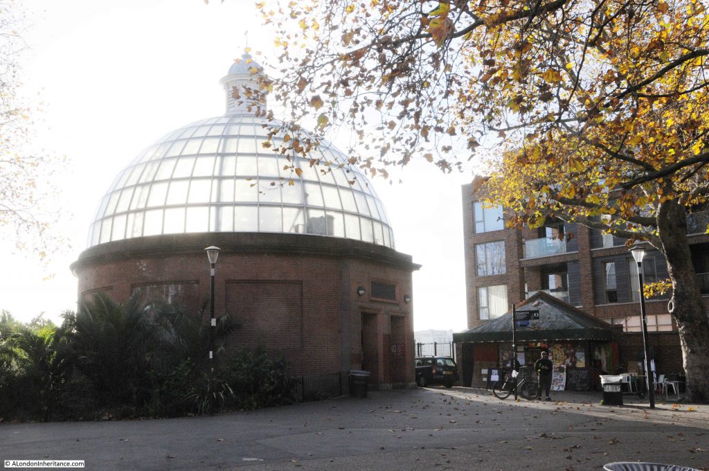
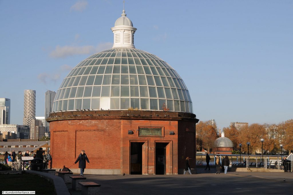
There are almost identical entrances to the Greenwich foot tunnel on both sides of the river. This is the entrance in Island Gardens, with a low sun directly behind the entrance:

Greenwich Foot Tunnel

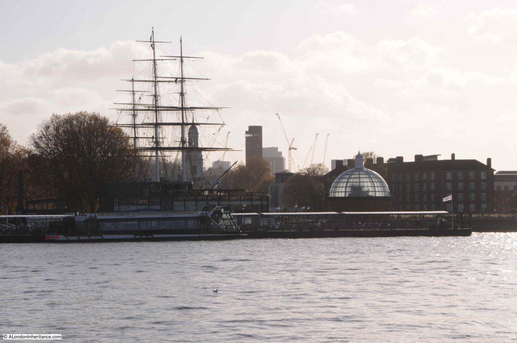
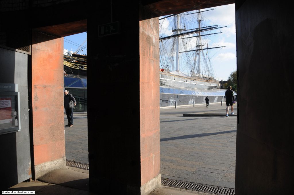
On the opposite side of the river, the translucent glass roof of the Greenwich entrance can be seen alongside the Cutty Sark:

View from Island Gardens

The Greenwich Foot Tunnel was one of a number of tunnels constructed under the River Thames in the late 19th and early 20th centuries. Those wanting to travel between the north and south sides of the river had long been restricted to a ferry, or long journey to the nearest bridge in central London.

A single tunnel Blackwall Tunnel had opened in 1897, the Greenwich Foot Tunnel in 1902, the Rotherhithe Tunnel in 1908 and the Woolwich Foot Tunnel in 1912.

A period of fifteen years that had opened up a range of new routes to travel between opposite sides of the River Thames, no doubt one of the benefits of having the London County Council responsible for major works across the city.

A foot tunnel for those who lived and worked on different sides of the river, or who had business that needed a crossing, had been identified as an urgent need for a number of decades in the second half of the 19th century, however it was not until the final five years of the century that the scheme would get underway.

On the 12th May 1896, newspapers were reporting that a Bill for the tunnel was to be put before Parliament:

“PROPOSED NEW THAMES TUNNEL. A LONDON COUNTY COUNCIL SCHEME – The Bridges Committee of the London County Council have prepared a report, to come before the Council today, recommending that application should be made to Parliament for power to construct a foot passenger tunnel to connect Greenwich and Millwall, at an estimated cost of £75,000, and that the Parliamentary Committee of the Council be instructed to prepare the necessary Bill, to be introduced in the Session of 1897.

The report states that, in addition to the above amount, which is the estimated cost of land and works for the proposed tunnel, a sum of not less than £25,000 as the law at present demands, would have to be paid as compensation to persons interested in a ferry which exists at the spot in question; but it is hoped that the Council will succeed in obtaining a clause by which ‘improvement of interest will be considered, thereby reducing this amount very considerably.’

The plan is to have a tunnel with a footway of eight feet, and a headway of rather more than nine feet in the centre, reduced to a minimum of seven feet and a half at the outsides. Electricity is to be used for lighting the tunnel, as also for working the ventilating and pumping machinery. The time required for the execution of the works is expected to be about twelve months, Calculations are given to show that the proposed tunnel would be a more economical provision than establishing a free ferry.”

The London County Council estimated a cost of £75,000 for the construction of the tunnel, and this was the value put forward in the Bill to Parliament, however as with almost every major civil engineering project since, the cost would turn out to be much higher.

The council invited tenders for the construction of the tunnel, and the winning tender was from Messrs. J. Cochrane with a price more than one third above the estimated cost. The Bridges Committee recommended that the council accept the bid, however the council were not happy and wanted the additional third of the estimated cost to come from “local or other sources”, however when put to the vote, the recommendation of the Bridges Committee was accepted and the work would soon commence.

The new tunnel was opened on the 4th of August 1902.

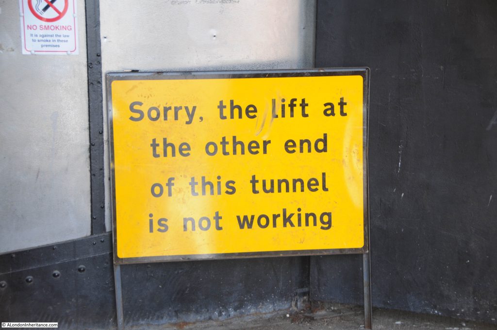
The route down to the tunnel is via several flights of stairs from the entrance in Island Gardens. The lifts are currently out of use.

Greenwich Foot Tunnel

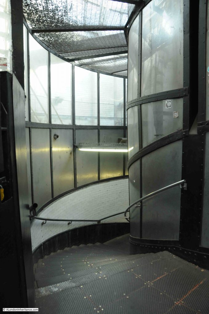
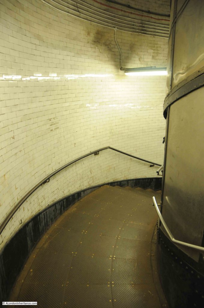
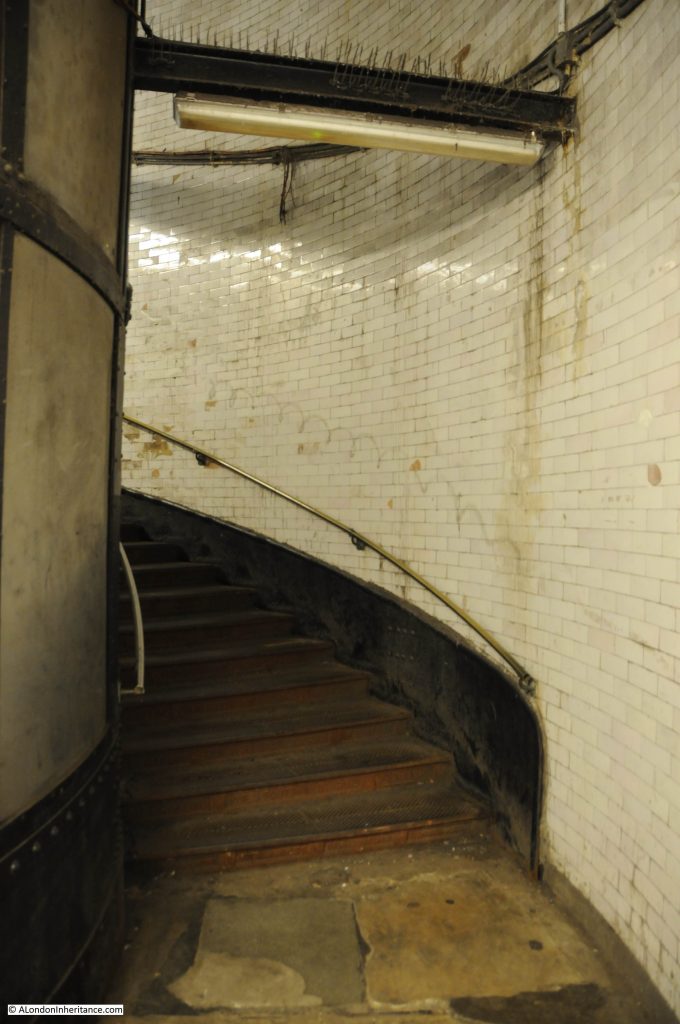
Spiral stairs line the inner wall of the shaft, with the central space being used for the lift:

Greenwich Foot Tunnel

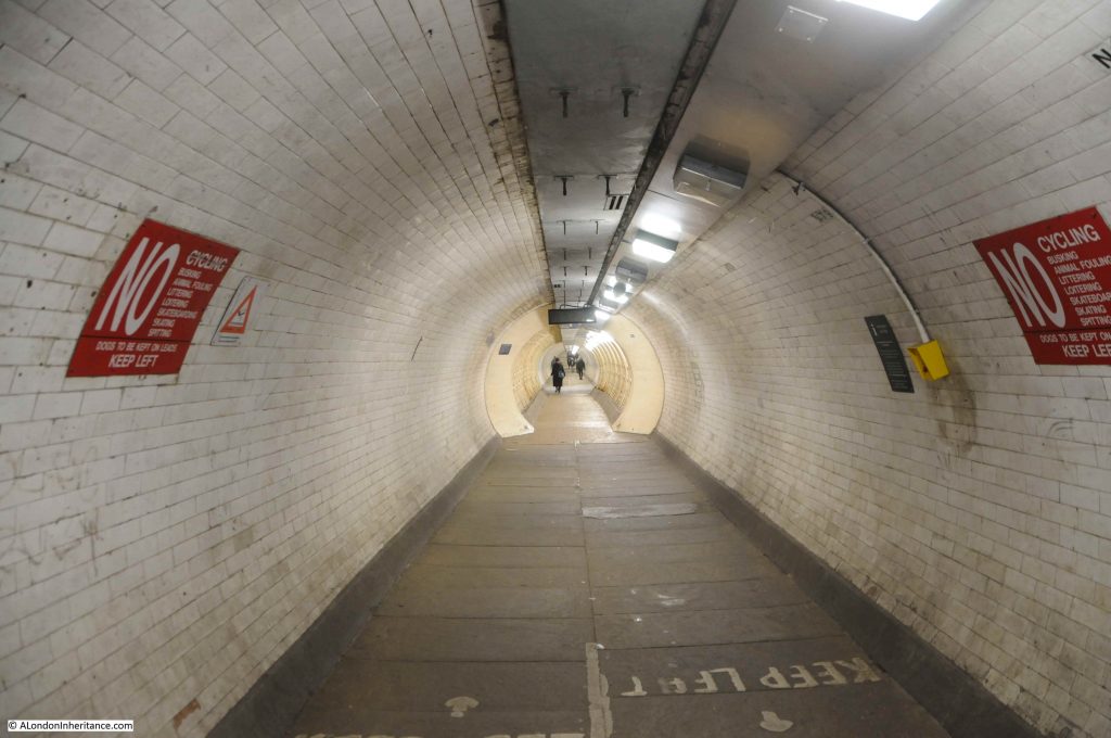
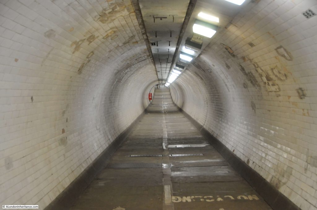
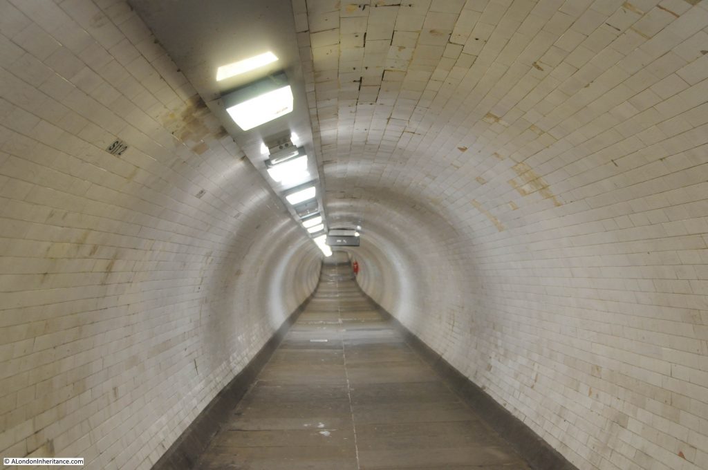
From the bottom of the Island Gardens shaft, the view along the tunnel towards Greenwich:

Greenwich Foot Tunnel

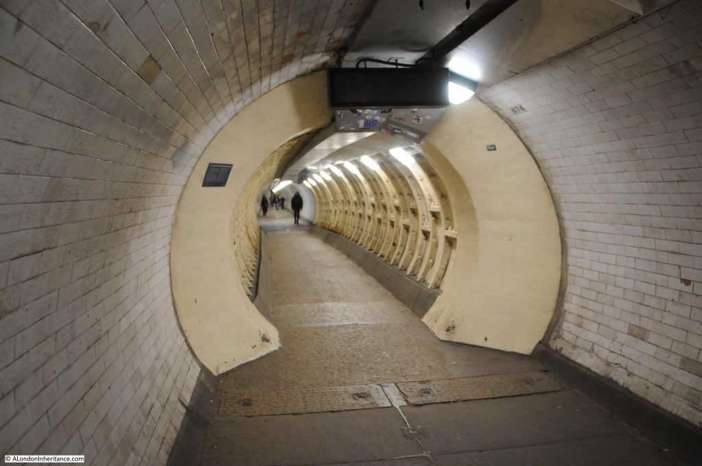
In the above photo, a cream coloured section can be seen a short distance along the tunnel.

The section is the temporary war time repairs following damage caused to the tunnel by the nearby explosion of a high explosive bomb. A closer view is seen in the photo below, and there is an information panel on the left:

Greenwich Foot Tunnel war damage

The damage to the tunnel happened on the evening of the 7th September 1940, when a bomb exploded on the foreshore, over the route of the tunnel.

Within the tunnel, the blast caused the outer tiles and inner concrete lining of the tunnel to collapse over the length of the tunnel now covered by the temporary repairs. The outer iron lining appears to have held, however this was now leaking and water was entering the tunnel to such an extent that a week after the bombing, the tunnel was full of water.

The tunnel was such a key part of the local infrastructure, providing workers living on the south of the river with easy access to the docks, ship yards and factories in the Isle of Dogs and east London, that a repair of the tunnel was essential.

It took around ten days to pump out the majority of the water, enough that work could start on repairs.

Being wartime, a temporary repair was put in place, consisting of a length of iron collars bolted together to line the damaged area, and effectively form a smaller tunnel within the larger tunnel. At the time, these repairs were considered sufficient to last the war, following which, more permanent repairs could be put in place, and the tunnel restored to its original size.

As well as infrastructure projects always running well over their initial budget estimates, temporary repairs also often become permanent, and so it is with the repairs in the Greenwich Foot Tunnel, and the cream coloured iron rings, reducing the diameter of the tunnel, are still the result of the original 1940 repair work.

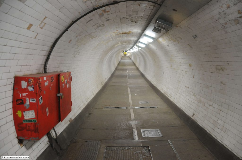
Walking through the temporary repairs and at the end we can see the tunnel continuing on down to the lowest point roughly under the center of the Thames.

Greenwich Foot Tunnel

Now we are roughly in the center of the tunnel, it is a good place to stop and consider the original construction.

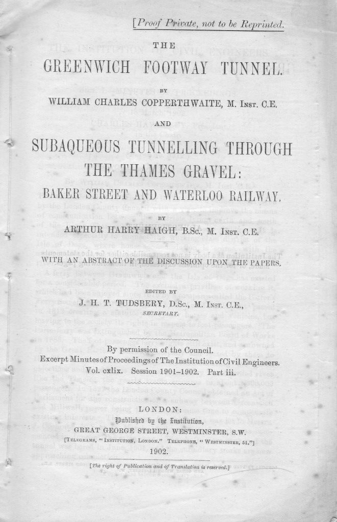
I have a fascinating little booklet called “The Greenwich Footway Tunnel by William Giles Copperthwaite and Subaqueous Tunneling Through The Thames Gravel: Baker Street and Waterloo Railway by Arthur Harry Haigh”.

The booklet is an extract of the proceedings of the Institution of Civil Engineers, and was published in 1902, the year the Greenwich foot tunnel opened. It is a wonderful little booklet with details of tunneling below London and the impact of the geology through which the tunnels are constructed.

Greenwich Foot Tunnel

The first part of work to build the tunnel was the sinking of the shafts down to the point where the tunnel could start to be bored under the Thames.

The shafts were formed by sinking a caisson around the edge of the shaft, as the shaft was gradually excavated. A caisson is basically a hollow ring of iron or steel that forms a tube from top to bottom of the shaft and provides the strength to stop the sides of the shaft collapsing inwards, or the walls deforming.

The shafts, as with the whole of the tunnel, were constructed in an environment of compressed air. This method was used to control the ingress of ground water and to provide some support to the ground through which the tunnel is being bored. The use of compressed air did require some additional support for the workers, and faclities such as air locks to provide access to the work face.

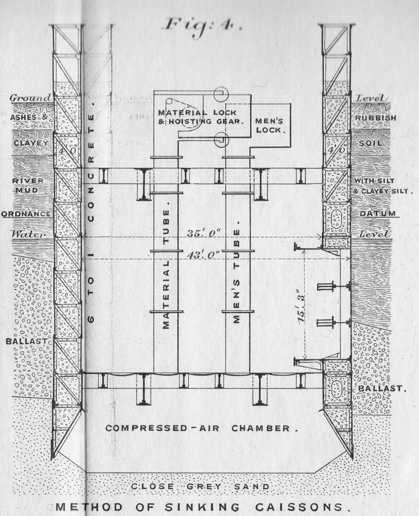
The following diagram shows the method of sinking the caissons. The shaft was sunk through the water level which was found at a depth of 35 feet, from which point, construction continued using compressed air.

Method of sinking the caissons

The caissons, today the walls of the shaft, are made up of two steel rings. The outer diameter of the shaft is 43 feet, and the inner diameter is 35 feet. Allowing for the width of the two steel rings (one outer, one inner), there was a four foot gap between the two rings of the shaft. This was filled with a mix of 6 to 1 Portland cement concrete. The use of concrete as a filling between the two rings meant that accurate construction and fitting of the rings was essential as once the concrete was poured, there was no way to make any further adjustments.

This method of construction created a pair of incredibly strong shafts on either side of the river, and the weight of the caisson forming the wall of the Poplar shaft was a remarkable 2,560 tons.

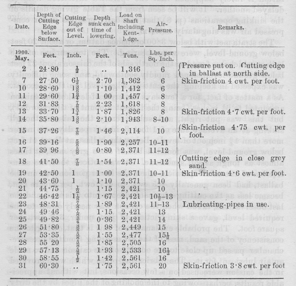
Compressed air was put in place from the 2nd of May, and the following table records the depth below the surface achieved each day until completion of the Poplar shaft on the 31st May, 1900.

Digging the shaft

The table also shows the accuracy of the excavation by the very small amounts that the cutting edge was out of level. The increasing weight of the caisson can be seen by the load on the shaft.

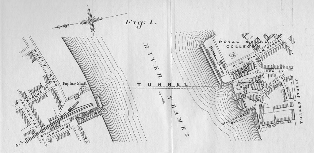
The following drawing shows the route of the tunnel between the Poplar and Greenwich shafts. Note that just above the Greenwich shaft is the Ship Tavern. This pub was badly damaged during the war, demolished, and the Cutty Sark is now on the site of the pub.

Route of the Greenwich Foot Tunnel

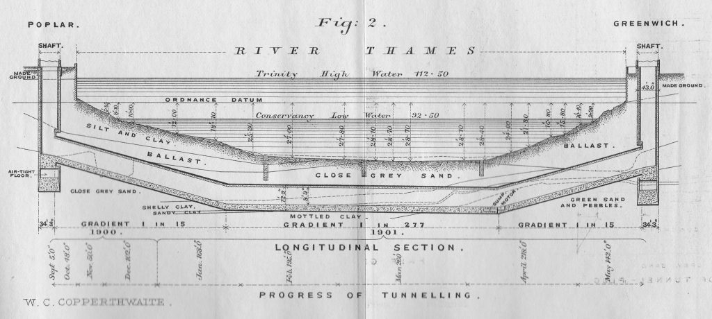
The following drawing shows a cross section of the tunnel. As will be seen in my photos of the tunnel today, the tunnel descends from both shafts with a gradient of 1 in 15 feet, down to the central part of the tunnel where it passes under the deepest part of the Thames.

Cross section of the Greenwich Foot Tunnel

The diagram also shows the type of material that was being excavated through, and was a key consideration in the tunneling method used.

The drawing is a text book example of how to present lots of information in a single drawing. As well as the key lengths, gradients of the tunnel, high and low water level of the Thames, depth of water, dimensions of the shafts etc. the Progress of Tunneling at the bottom of the drawing shows how the tunnel was making its way under the river through 1900 and 1901 as it started from the Poplar shaft and headed to the Greenwich shaft.

Newspapers reported on reaching the half-way point:

“IT IS NOW HALF-WAY TOWARDS COMPLETION – A new tunnel between Poplar and Greenwich is another step in the piercings of the river bed which the London County Council splendidly inaugurated with the making of the Blackwall Tunnel.

The new tunnel will be opened to the public in about a year’s time, and, inasmuch as it is being made wholly in the interests of working men, it might be called the ‘Working Men’s Tunnel’. From shaft to shaft it will measure 1217 feet in length, and will cost about £109,500. The depth of the tunnel at the centre of the river is about 72 feet below the ground line, while the shafts have been sunk to an average depth of 63 feet.

At no part will the top of the tunnel be less than 13 feet below the river bed. No fewer than 1600 tons of cast iron tubing will be used in building the tunnel which will be lighted by electricity. You will approach the tunnel from the Greenwich side from the north end of Church Street, in the rear of the famous Ship Tavern; and on the Millwall side at the Western end of Island Gardens. Some such easy means of communication between one shore and another has long been needed, and many thousands of people will daily find it very handy once it is opened to the public.”

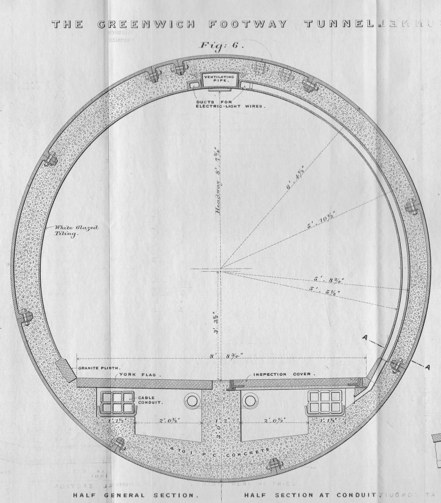
The lining of the tunnel was made up of cast-iron segments, of which eight segments and one key piece formed a complete ring around the tunnel. The lining was 12 feet, 9 inches in outer diameter and 11 feet 9 inches internal diameter.

The following drawing shows a cross section of the tunnel, including the lining, and ducts for services such as electrical wiring, ventilation pipes and cable conduits.

Greenwich Foot Tunnel

The interior of the tunnel was lined with white glazed tiling, which is still in place today.

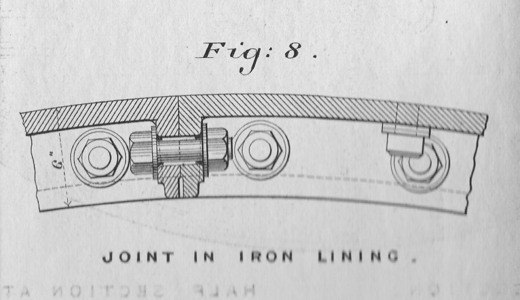
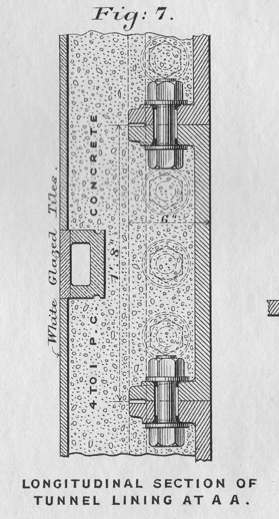
The booklet includes some wonderful detail of sections of the tunnel lining:

Tunnel lining

The washers where the bolts secured the sections together were made using a short section of lead pipe. When the bolt was tightened, the lead would compress forming a water tight seal around the bolt.

Lead wire and iron filings were used to fill any spaces between sections, and the method of construction was so successful, that when air pressure was removed at the end of construction, only a dozen places had a small problem with water ingress and needed repair.

Tunnel lining

The tunnel was constructed using a shield of the type known as a trap or box shield, which the booklet describes as follows:

“The trap consisting of two diaphragms, the front one filling the upper half and the back one the lower half, of the circle enclosed by the cylindrical skin of the shield.

The bottom of the front diaphragm is a few inches lower than the top of the back one. In the event of an inrush of water from a ‘blow’ occurring at the face, the water must flow over the top diaphragm to get into the tunnel, and before it rises high enough to do this, the bottom of the top diaphragm is under water, and all escape of air through the shield is stopped. the water in fact becomes a seal to hold the air.”

The above description simplifies the design, construction and use of the shield, and cross sections through the shield as used at Greenwich are shown in the following drawings.

Tunnel shield

The central box formed a water tight chamber, and the shield consisted of thirteen rams for pushing the shield forward, and together exert a pressure of 1.5 tons per square inch, and a total thrust to push the shield forward of 750 tons.

The design of the shield was changed as it progressed on its route under the Thames, as improvements were identified and as different types of strata were encountered.

This included putting doors in the upper part of the shield, as well as the lower, giving workers an additional method of exit if there were problems at the face of the tunnel. It was noticed that after these additional doors were added, workers were more inclined to stay at the face of the shield after there had been a fall of material, as they had a higher route of exit than before.

As well as the safety of workers at the shield face, another consideration was the conditions of working in an environment where compressed air was used. As well as care of their workers, there was also probably a financial motivation as the Act of Parliament authorising the tunnel included compensation to those whose health had been damaged by working in compressed air. Compensation seemed rather limited though as a total of £20 had been awarded to three workers.

Two medical officers were appointed to oversee the construction of the tunnel. Those working in the tunnel were examined at least once a week and before anyone could commence work, they had to have a certificate of health from the medical officers.

Of those who applied to work on the tunnel, 13.9% were found to be unfit to work on initial examination, and of those who passed the medical, a further 5.7% were found to be affected by the increased air pressure, and forbidden to continue work in the tunnel.

Men worked an 8 hour shift with a rest period of 45 minutes, during which time they had to exit the tunnel.

Rooms were available with washing facilities at the construction site for the workers, and hot coffee was served as they left the tunnel.

A “medical lock” was available for treating those with “caisson-sickness”, probably similar to today where a diver has to decompress in a chamber. Only three workers needed to make use of this facility during the construction of the tunnel.

A concern with tunnel construction was the potential build up of carbon dioxide, and as the construction of the tunnel progressed, an experiment was approved whereby an apparatus was made and installed to removed carbon dioxide. This consisted of a series of wooden boxes bolted together. In each wooden box there was an amount of crushed pumice stone. Air was passed through the boxes, and it was found that deposits of carbonate of soda were found on the pumice stone, and that the experiment did result in the removal of some of the carbon dioxide in the air within the tunnel.

Construction of the tunnel was relatively straight forward given the technologies of the time, and construction methods were able to adapt to the changing sand, clay and ballast through which the tunnel was being bored. For a period between the 22nd February and the 1st May 1901, an impressive 10 feet per day was being achieved in driving the tunnel forward.

The tunnel met the Greenwich shaft without any problems, and minor precautions were made to stop any fall of sand or ballast from the area around the shaft as the tunnel was completed.

The Isle of Dogs and Greenwich were finally connected by a walking route.

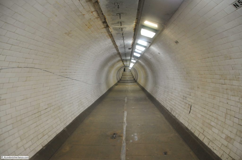
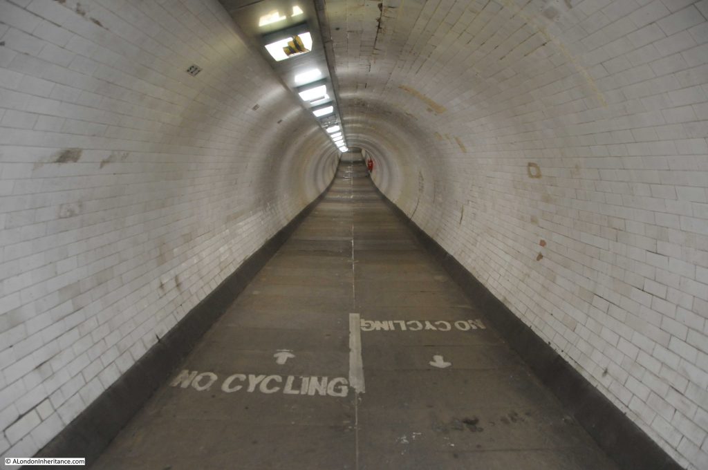
In the following photo, the incline up to the Greenwich shaft from the centre of the tunnel can be seen:

Greenwich Foot Tunnel

I am not sure whether it was my imagination, however standing in the centre of the tunnel, it seemed possible to hear the sound of the occasional passing boat on the river above.

At the start of the incline where the tunnel rises by 1 foot in every 15 feet, up to Greenwich:

Greenwich Foot Tunnel

Almost at the Greenwich end of the tunnel looking down the incline:

Greenwich Foot Tunnel

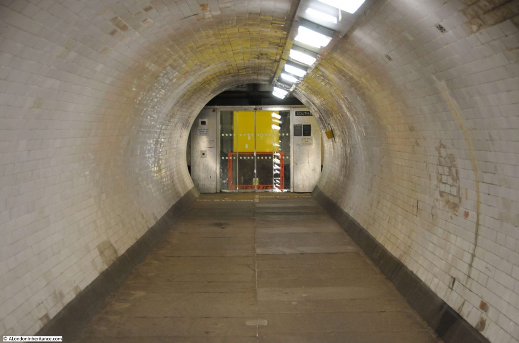
Approaching the Greenwich end of the tunnel, and it looks as if we are approaching an entrance to some secret infrastructure below London – unfortunately it is only the closed entrance to the lift which should be operating.

Greenwich Foot Tunnel

The tunnel today is brightly lit and there is a frequent flow of walkers through the tunnel. It has not always been this way, and as the docks and industries closed on either side of the river the numbers walking through declined and there were times during the 1980s when you needed to be cautious when using the tunnel.

A final look down the Greenwich foot tunnel:

Greenwich Foot Tunnel

The Greenwich shaft is slightly deeper than the Island Gardens shaft. I counted 87 steps down from Island Gardens, and was rather surprised to count a round number of exactly 100 steps up the Greenwich shaft:

Stairs

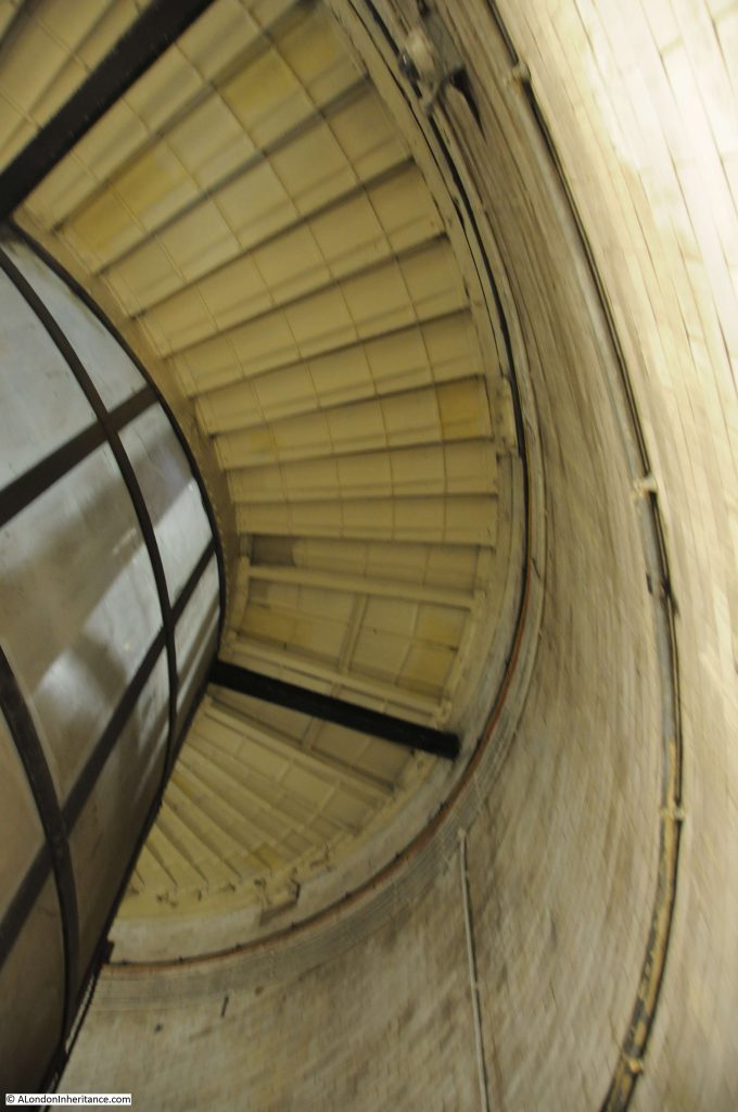
Whilst walking up the shaft, a look up shows the cantilevered steps of the spiral above:

Spiral staircase

At the top of the steps, one of the current landmarks of Greenwich confirms that you have arrived on the south bank of the River Thames:

View of Cutty Sark

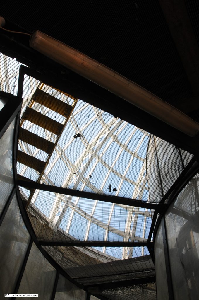
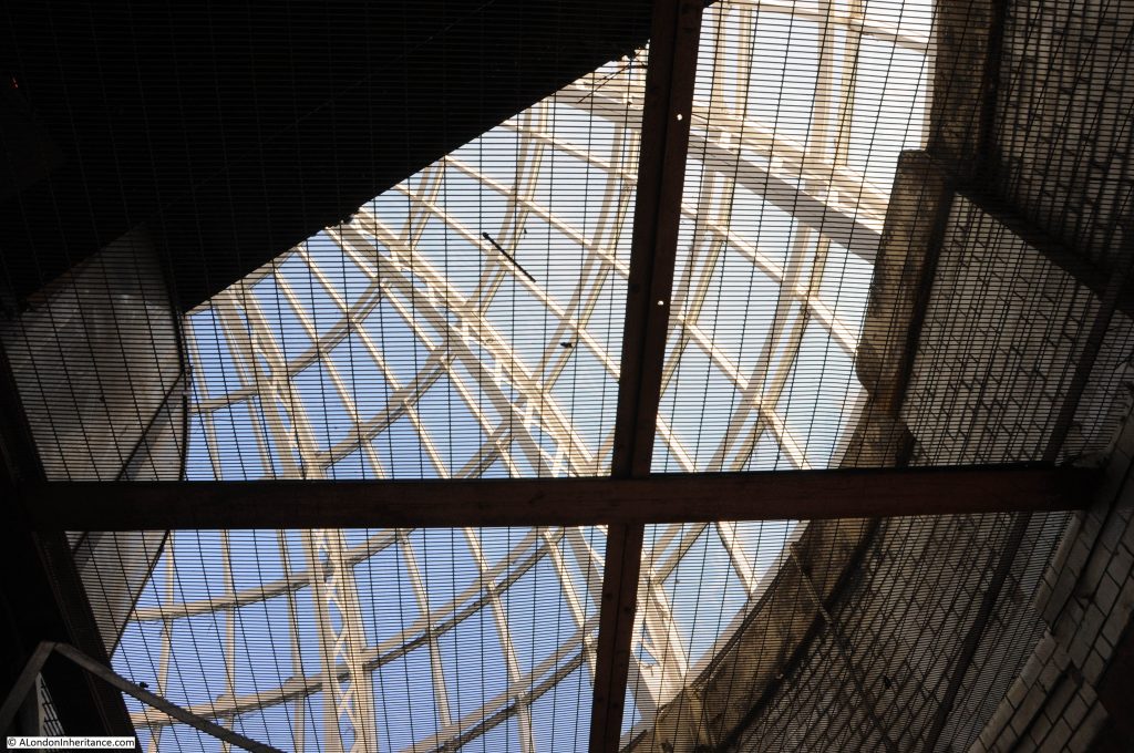
But before leaving, another look up shows the wonderful construction of the glass dome that covers the entrance to each shaft:

Entrance to foot tunnel

As well as the bomb damage to the tunnel, the entrance buildings and shafts were also damaged by bombing, with an oil filled incendiary hitting the Island Gardens shaft, causing considerable damage to the lift control equipment. The Greenwich entrance was also hit by an incendiary bomb, but did not suffer as much damage as at the northern shaft.

Entrance to foot tunnel

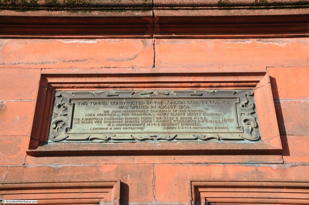
Plaques above both entrances to the tunnel record the opening in August 1902, along with key figures in the London County Council responsible for the tunnel:

Plaque of foot tunnel entrance

A view of the Greenwich entrance to the tunnel, with the Island Gardens entrance across the river, just to the right:

Greenwich Foot Tunnel

The original lifts were added in 1904, two years after the tunnel opened, these were attendant operated until the early 21st century. New lifts were installed in 2012, however there have been periods when the lifts were not that reliable, with significant problems with the glass doors closing reliably, and they are currently closed.

Greenwich tunnel lifts

A major problem with the lifts is that they are almost a custom design, having to fit inside the original lift space in the centre of the shaft, and also within such a historic structure.

Special parts for the lifts are sourced from Germany, and it is still expected that the lifts will be closed for some months.

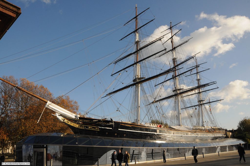
Outside the tunnel entrance is an excellent view of the Cutty Sark:

Cutty Sark

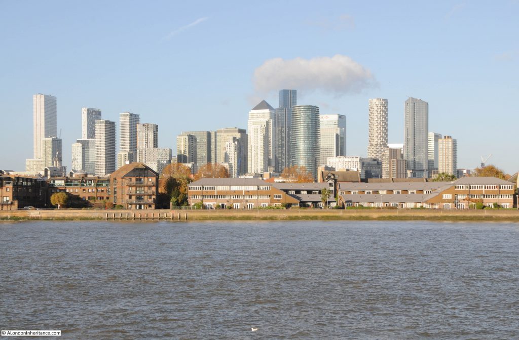
And looking across the river is the ever expanding collection of towers that are growing across the Isle of Dogs:

View of the Isle of Dogs from Greenwich

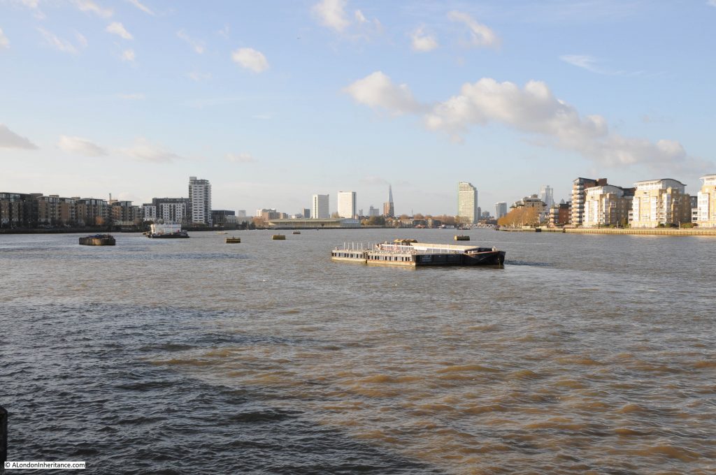
View to the west, towards the City of London from close to the Greenwich entrance to the tunnel:

View of the Thames from Greenwich

Looking east from the entrance to the Greenwich foot tunnel:

View of the Thames from Greenwich

The Greenwich foot tunnel was certainly a success, and a major improvement on the ferry which the tunnel replaced.

A ferry had been operating between the Isle of Dogs and Greenwich for hundreds of years, and such was the level of traffic, that from 1883 the Thames Steamboat Company operated a steamboat ferry, which did have problems operating in a very crowded section of the river (hard to believe when looking at the view today just how busy the river has been).

Despite this, the steam ferry was carrying around 1,300,000 passengers a year, which seems remarkably close to the 1.2 million a year that the Royal Borough of Greenwich state on their website as using the tunnel today.

The booklet states that the foot passenger ferry rights continued to exist after the opening of the tunnel and were owned by the Great Eastern Railway Company.

It would be interesting to know if these rights still exist and whether Network Rail could today run a passenger ferry across the Thames at Greenwich.

alondoninheritance.com

The Willesden Oil Well

For just over a week, the blog has had a fault connecting with the subscriptions package, so although I wrote a new post last Sunday, it appeared on the blog, but did not get e-mailed out. The connection has been rather unstable for the last few days, but now looks better, so I hope the problem is fixed. To test, here is a post with the strange story of when Willesden was the centre of oil exploration in London.

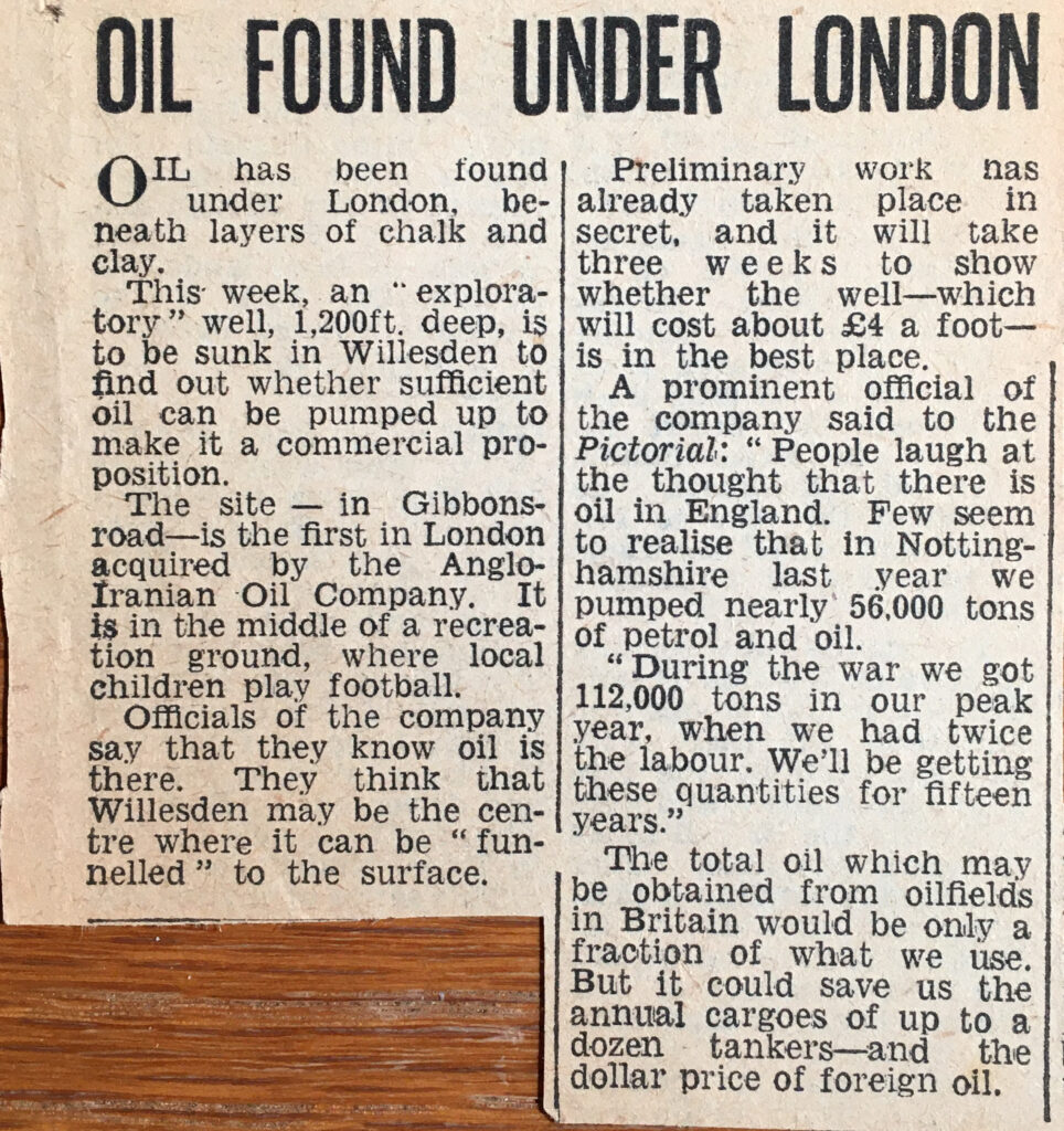
I have mentioned before one of my fascinations with old books is that you never know what previous owners may have added between the pages. I was looking through a copy of Haunted England by Christina Hole (1941 – A Survey of English Ghost-Lore), and between the pages were a couple of clippings from newspapers about an oil well that was drilled in Willesden in 1947:

After the war, the country was desperate for foreign currency, and was trying to export as much as possible, as well as to limit any imports that would have to be paid for in a foreign currency, such as dollars.

One of the major dollar imports was oil and as the article mentions, any source of oil that would enable a reduction in imports would have been highly important to the economy.

The fact that there were traces of oil deep below the streets of Willesden had been known for a number of years. In 1911 a laundry business in Willesden had been drilling a borehole as a water source, but instead found traces of oil. This resulted in a search for oil by drilling the borehole much deeper to see if there might be commercial quantities available, as reported in the Pall Mall Gazette:

“Is oil present in paying quantities in Great Britain? Is this country to be to some slight extent independent of its coal measures?

That is an interesting question which, often mooted before, is prompted again by the recent announcements that oil had been discovered in a well-boring at the White Heather Laundry, Willesden. In the days when ‘booms’ are only too readily created, the owners of the Willesden property showed commendable reticence in refraining from making public their discovery until the news leaked out through a channel which has not yet been discovered.

It must be remembered that the oil obtained at Willesden so far only amounts to a very small quantity, and the question whether it is there in commercial quantity is not likely to be settled for some time; the boring was started in January, 1911, and the first indication of oil was obtained at a depth of 1,200ft on September 6th. The depth of the boring is now 1,735ft. The people concerned are now definitely ‘going for oil’ and the success or failure of their experiment will be watched with absorbing interest”.

There were further positive news reports including:

“One of the directors of the laundry (which was founded about ten years ago by four young men from Cambridge) said: ‘We have had several members of City companies up here already, including representatives of the Standard Oil Company. We had found a splendid quality of water at a depth of 1,000ft, but the quantity is short of our requirements, and that is the chief reason why we are going deeper. We prefer to test the real value of the oil discovery before making any sort of deal”.

The borehole found very salty water at a depth of 1600ft, which was assumed to be water from an old sea formation.

Water was rising to the top of the borehole, and variable amounts of gas would also bubble up through the water.

The 1911 borehole did find traces of oil deep below Willesden, but not sufficient quantities to be economically viable, so the “four young men from Cambridge” did not make their fortune from oil.

Another attempt at finding oil was the 1947 borehole in the article at the start of the post. It may well be that the need to restrict imports encouraged another attempt at finding oil after the failure of the 1911 borehole.

The 1947 borehole was drilled by the D’Arcy Exploration Co. Ltd, a subsidiary of the Anglo-Iranian Oil Company. This was the oil company that was formerly known as the Anglo-Persian Oil Company, which was the first oil company to extract oil in Iran. The company would later become British Petroleum (BP), so this new exploration in Willesden was being undertaken by a company with some serious oil exploration heritage.

The cost for drilling the borehole and examining the results came to a total budget of £10,000, a considerable sum for such a speculative undertaking.

Expectations were high, and the planned borehole made the national press with the Daily Mirror reporting that there was a strong possibility of oil being found, and that “One of the officials on the site yesterday said ‘I think the prospects are good’ “.

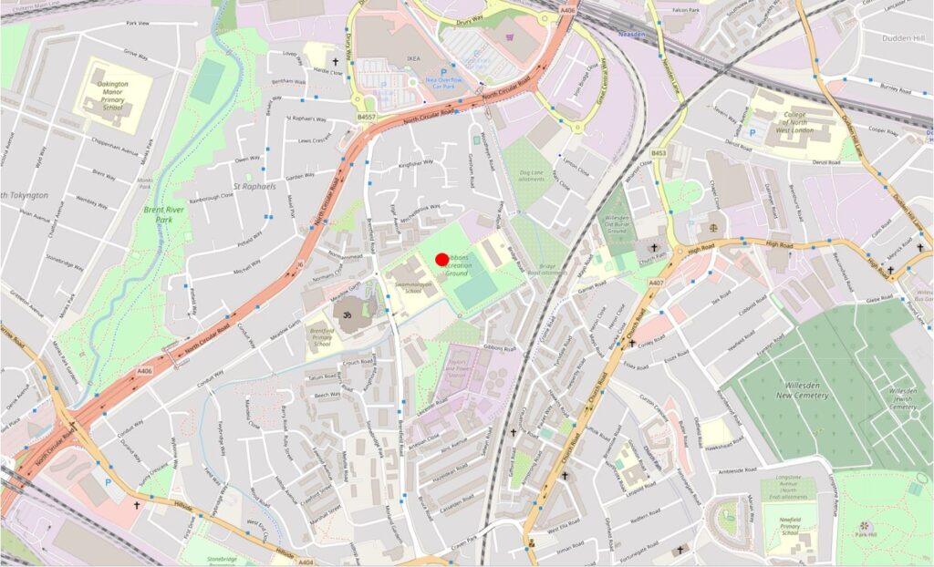
Work on the borehole commenced in November 1947, with even the serious Illustrated London News stating that “North London could become another Kirkuk” (the city in Iraq that was producing 4 million tons of oil a year before the war). The borehole was being drilled in the Gibbons Road Recreation Ground, an area of open space we can still find today. In the following map extract, a red circle marks the approximate location of the borehole (Map © OpenStreetMap contributors):

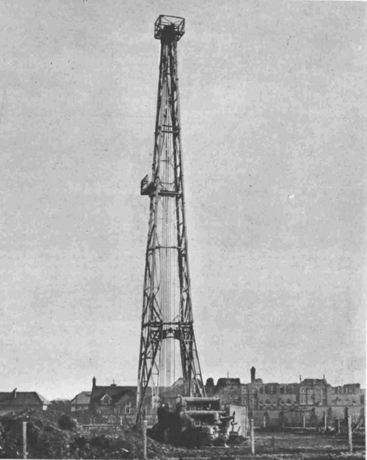
An 87 foot high “jack-knife” derrick was used, powered by a Caterpillar diesel engine. The following photo gives an impression of the derrick in operation:

The borehole went down to the remarkable depth of 2,680ft, and the original bore hole logs by the D’Arcy Exploration Company can still be found online. The British Geological Survey has an online portal which maps all the boreholes that have been notified to them, and clicking on each borehole location will identify if the logs are online with a link for access (see link at the end of the post).

It is remarkable how many boreholes there are across London, and it is fascinating to look for patterns in their locations on the British Geological Survey site.

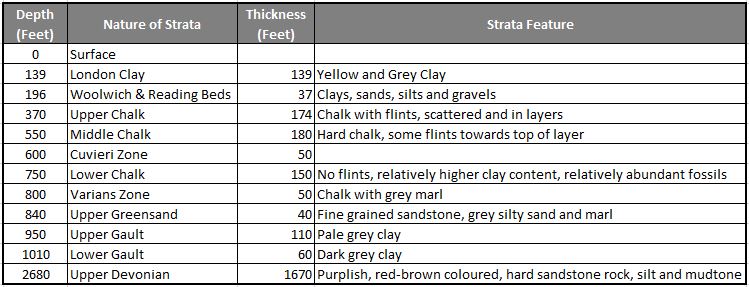
The borehole log for Willesden reveals the following rock strata as the drill headed 2,680ft below the surface of London.

The log pages reveal interesting details of what was found at different levels.

Pyrolised wood was found at about 60 feet (pyrolised refers to the decay of wood in the prescence of heat).

The Cuvieri Zone seems to refer to a zone where a specific type of plankton fossil called Orbulina was found.

A fractured zone with fish remains was found at a depth of 1085 feet.

Although trace amounts of oil were found, it was clear that Willesden would never be an oil producing area, and drilling of the borehole ended in January 1948. The borehole record contains the single word “Abandoned” at the end of the list of strata.

The borehole was capped, and concrete was used to fill the hole from a depth of 1000 feet to the surface – strange to think that this long concrete column now sits below Gibbons Road Recreation Ground – for comparison, roughly the same height as the Shard, and the overall borehole drilled down two and half times the height of the Shard.

Drilling had been met with an air of excitement in newspaper reports at the start of work, however by January 1948, the only reports were a small paragraph stating “Experts have abandoned hope of striking oil at Willesden, but work will continue to obtain general geological information”.

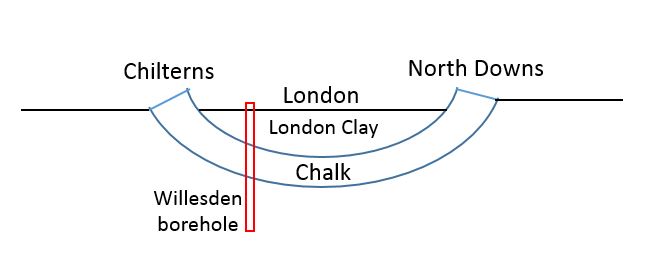
The geology of London is fascinating. In the Willesden borehole, thick layers of chalk were found. These form a sort of bowl underneath the city, curving below the city, rising up to form the Chilterns to the north of the city, and North Downs to the south.

The following graphic shows how the chalk layer dives under the city. The Willesden borehole drilled through London Clay and Chalk layers to the much older rocks below.

London Clay formed as a sediment at the bottom of a sea, formed around 56 to 34 million years ago. The chalk layers are much older and also built up on the bottom of a warm sea in the Cretaceous period over 65 million years ago.

The geology of London goes some way to explaining why there are far more Underground train routes north of the river than to the south. London Clay is a relatively easy substance to tunnel through, and although I have shown it equally spaced in the above graphic, in reality there is far more London Clay to the north of the river than the south.

London Clay is impermeable – water does not easily pass through the clay, chalk is permeable and explains why boreholes such as the 1911 borehole for the Willesden Laundry, were sunk to access water. Rain from outside the area of London Clay would flow through the chalk and water would collect in the layers of chalk under the city.

The British Geological Survey map of boreholes provides so much information on the geology below London. The chalk layer has provided London with water for centuries. The record for a borehole at 1 Bankside, performed in the late 19th century for the Belfast and London Aerated Water Company identified a minumum water flow of 3,000 gallons an hour. Water was found at a depth of 114.5 feet. The purity of the water was measured at 27.1 parts per 100,000 of total solids, or which 12.7 were Chlorine.

A note at the bottom of the borehole record states that the site was visited on the 11th July 1946 and that the borehole had not been filled in, but was boarded over and had not been used for some 30 to 40 years. The note remarked that the borehole probably could not be used anymore due to dirt and rubbish.

St Paul’s Catherdral sits on a hill, however in the distant past water has washed over this area. A 2008 borehole at One New Change identified a 6m thickness of River Deposits below the built layer near the surface. this layer consisted of dry sand and gravel for the first 4.5m, followed by a 1.5m layer of wet sandy gravel.

This may all seem rather remote as we walk the streets of London, however the strata below the surface impacts the location and design of so much of the infrastructure we take for granted.

For example, with the extension of the DLR from the Isle of Dogs to Greenwich and Lewisham a detailed geophysical investigation was undertaken along the route of the tunnel under the Thames. There was concern that a geological fault, (a fracture between two different blocks of rock) could have caused problems for the tunnel. The fault line was found slightly to the east of the tunnel’s proposed route.

The Thames Barrier sits astride the Greenwich Fault, and there are horizontal and vertical shifts of up to 50 meters and 5 metres respectively between the rock strata in the area around the barrier.

Seventy three boreholes were drilled during the planning of the Thames Barrier to check the ground beneath. There was concern that the chalk under the southern half of the site had been damaged during the ice age when frozen conditions could have resulted in the top layers of chalk crumbling into rubble, which would not have created a stable base for construction. Fascinating that we still have to consider the impact of the Ice Age on present day construction.

If you have exhausted the TV schedule, and Netflix, run out of alcohol, and the pubs are still not open, why not spend an evening browsing the British Geological Survey borehole portal. There are hundreds across the city. (The link brings up the UK map, click on the borehole scans at top left, geology transparency at top right to 100%, then zoom in to parts of London where the coloured dots of boreholes appear. Click on one of the dots to bring up information as to whether there is a scan available).

Boreholes for the Jubilee Line Extension, the new Thames Tideway Tunnel, historic boreholes drilled for water, such as the 600ft borehole beneath BBC’s Broadcasting House that was yielding 1,272 gallons of water an hour. Confidential or Restricted boreholes are spread across London. There are no online records for these, and it is intriguing to guess at the reason.

There was a potential attempt at drilling again at the original Willesden site, when London Local Energy applied for a licence to drill and search for oil and gas in 2014. The company believed that whilst small quantities had been found in the earlier boreholes, new fracking technology would allow an economic quantity to be recovered. The application did not make any progress.

Despite the considerable number of boreholes, no commercial oil has ever been found in London, so Willesden, or anywhere else in London will never see an oil bonanza.

alondoninheritance.com

Limehouse Cut and Angel Underground Station

Before starting on this week’s post on the Limehouse Cut and Angel Underground Station, can I thank you for all the feedback following last Sunday’s post. It is really appreciated.

I also hope that if you receive my posts as a subscriber, this one does reach you. For the last few days there has been a rather obscure error message in the component that links the blog with the WordPress tool that manages e-mail subscriptions. The hosting company is investigating, so my apologies if it does not reach you automatically.

You may well be wondering what on earth brings the Limehouse Cut and Angel Underground Station together in one post. I can assure you there is a common theme linking these two locations, which I hope will become clear as you read through the post.

Limehouse Cut

If you walk east along Narrow Street in Limehouse, over the bridge that crosses the channel from Limehouse Basin to the Thames, then turn towards the river along the Thames Path, and at the end of the new apartment buildings that go by the name of Victoria Wharf, you will find a short channel in from the river:

This was the original river entrance where the Limehouse Cut connected to the River Thames.

The Limehouse Cut was opened in 1770 to provide a direct route between the River Thames and the River Lea at Bromley-by-Bow.

The River Lea entered the Thames to the east of the Isle of Dogs, so the Limehouse Cut provided a much shorter route for barges heading to the City and east London by avoiding the need to travel around the full loop of the Isle of Dogs.

The following extract from the 1816 edition of Smith’s New Plan of London shows the Limehouse Cut running as an almost straight line from the River Lea at top right to the Thames, where I have marked the point where the Limehouse Cut connects to the river with a red circle – this is the short channel in my photo above.

The area to the lower left of the Limehouse Cut was mainly open space, with a limited number of buildings and streets, however this would be changing very soon.

Soon after the 1816 map was published, another canal was built to help with transport across the city. The Regent’s Canal ran from Limehouse and headed north to loop around north London, allowing goods to be transported from the river to the north of the city, thereby avoiding the congested road system.

Part of the Regent’s Canal included a large basin, an expanse of open water just before the point where the Regent’s Canal entered the river. There were warehouses around the basin, and barges would gather, waiting to transit to the river when tides allowed the locks to be open.

The Regent’s Canal Basin, and the entrance to the river was built immediately to the west of the Limehouse Cut.

For eleven years between 1853 and 1864, the Limehouse Cut was diverted into the Regent’s Canal Basin, however after 1864 the original entrance was back in use, with a new bridge carrying Narrow Street over the canal. This would last for another 100 years.

The following extract from the 1955 revision of the Ordnance Survey map shows the Limehouse Cut running from top right down to the River Thames, with the Regent’s Canal Basin immediately to the left, labelled as “Dock” (‘Reproduced with the permission of the National Library of Scotland’).

By 1968 industrial activity in the area had been in long decline as was trade on the Regent’s Canal and Limehouse Cut. The entrance to the river was again closed, and the Limehouse Cut diverted into the Regent’s Canal Basin that was renamed as the Limehouse Basin.

The following extract is from a map of the area today. Limehouse Cut is coming in from top right and diverting straight into Limehouse Basin, I have again circled the original entrance with a red circle (Map © OpenStreetMap contributors).

The pink road that appears to loop across the north of the Limehouse Basin is in reality underground as this is the Limehouse Link Tunnel.

The following view is looking across the old entrance to Limehouse Cut. The wooden boards may well be the original planks that lined the entrance to the canal.

A couple of high explosive bombs landed in the immediate vicinity so the area surrounding the wooden planks may well be repaired bomb damage.

A very faded information board at the old entrance to the Limehouse Cut:

Between 1853 and 1864, the Limehouse Cut had been diverted to the Thames via the Regent’s Canal Basin. In 1864, the original entrance was restored, and a new wrought iron girder bridge was installed to carry Narrow Street over the Limehouse Cut. This 1864 bridge remains in place, although because of the filled in entrance, the bridge is not that obvious apart from the iron side walls as the street is carried over the Limehouse Cut. This is the view from Narrow Street looking south towards the Thames:

The view looking north:

Looking over the northern edge of the bridge, we can see the section of the Limehouse Cut that was originally the lock that controlled access between the non-tidal canal and the tidal river. Much restored late 19th century lock keepers cottages line the western side of the old lock (to the left in the photo below):

The old Regent’s Canal Basin, now the smaller Limehouse Basin, today hosts a marina, and provides links with the River Thames, Regent’s Canal and via the Limehouse Cut, the River Lea, and are all really interesting walks.

The old Limehouse Cut entrance is evidence of the canal’s original 1770 route into the River Thames for one of London’s early transport systems.

Angel Underground Station

Today, the entrance to Angel Underground Station is on the corner of a modern brick office block, facing onto Islington High Street. It has not always been in this position.

To find the original station, you need to walk south to the junction of Islington High Street with Pentonville Road, and walk a short distance along City Road and on the left is a rather strange looking building:

This is the original Angel Underground Station.

The Angel Station opened in 1901 as part of the City and South London extension from Moorgate. Six years later in 1907, the line was extended on towards Euston station. Today, Angel Station is on the Bank branch of the Northern Line. The following extract from the 1954 Ordnance Survey Map shows the original station in the centre of the map, on the corner of City Road and Torrens Street. This is the station building photographed above (‘Reproduced with the permission of the National Library of Scotland’).

The location of the old and new stations can be seen in the following map (Map © OpenStreetMap contributors):

When Angel Station was built, it had a narrow central platform, with both tracks running either side of the platform. Whilst this was probably fine for the short period of time before the line was extended, it was a rather dangerous place when the platform was crowded, and busy trains ran in both directions.

The following clip is from the 1989 BBC film Heart of the Angel (link at the end of the post), showing the crowded platform.

From the same film is a clip of the 1989 entrance to the station, looking down City Road and is on the right of my photo of the station at the top of this section of the post.

The platforms were also served by lifts from the ground level building. The exterior cladding around the original brick building was a later addition to provide extra space. The view down Torrens Street with the station on the right:

By the late 1980s, the station had a long history of overcrowding along the narrow single platform. It would frequently be rather chaotic when two trains pulled in, with passengers leaving both trains onto a narrow platform full of passengers waiting to get on the trains.

The lifts were also relatively small for the number of passengers at busy times and would also frequently break down. At the end of the 1980s a major rebuild of the station began.

A new tunnel was excavated to take the northern branch, thereby separating the northern and southern tracks so each could have their own platform. The southern branch today occupies the space of the original tunnel so has a rather wide platform compared to a normal station, as the platform occupies the space of the original platform and the northern tracks.

Escalators were installed to avoid the use of lifts, and these took passengers between the platforms and the new station entrance on Islington High Street.

The new station opened in 1992, leaving the original station building to sit on the corner of City Road and Torrens Street.

Crossrail 2 includes a station at Angel, and the complete eastern side of Torrens Street, including the original station building, was designated in the safeguarding map of sites for Crossrail 2 construction and operation.

The following view looks along Torrens Street at the buildings included in the safeguarding map.

The buildings along this side of the street are an interesting mix of old warehouses.

Candid Arts Trust occupies a 19th century warehouse:

And at the end of the street is an early 20th century building that was constructed on the site of a smithy and may have been used to stable horses, however it would be occupied by a metal working and plating company.

And there is still evidence of this activity:

The building is now occupied by the “Islington Metal Works” – run by a hospitality company and the site is used for Wedding Receptions, Corporate and Christmas events.

The link between these two very different sites, in different parts of London is hopefully now clear; that they are the redundant entrances to once busy transport links that have now been diverted.

The entrance to the Limehouse Cut was once a busy route for barges moving between the Lee River and the River Thames, with the Limehouse Cut now diverted into Limehouse Basin.

The original entrance to the Angel underground station has now been closed for some thirty years, with passengers now diverted along escalators rather than lifts to the new station entrance on Islington High Street, with a considerably improved and safer platform layout at the station.

There are many examples of these across London where the ever changing transport system adapts to changing technology, different patterns of use and improvements.

A film was made for the BBC 40 Minutes series in 1989 documenting 48 hours in the life of the Angel station.

Heart of the Angel was made by the BAFTA award winning director Molly Dineen, and it is a very honest portrayal of a station struggling to cope with the numbers of passengers using the station and the creaking infrastructure supporting the station.

if you have a spare 40 minutes, it is well worth a watch and can be found here.
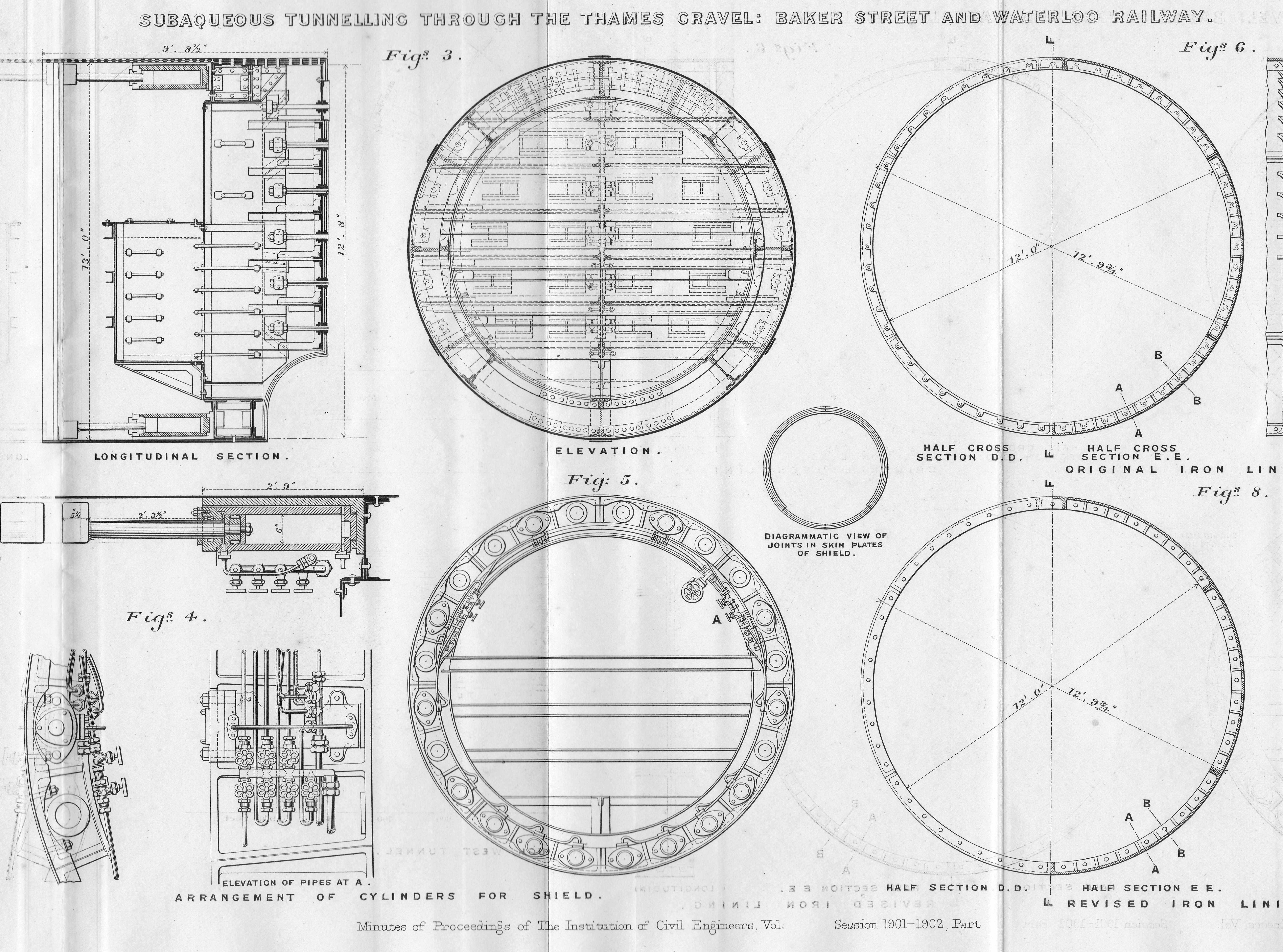
alondoninheritance.com

Billingsgate Excavation and London Docklands

Two apparently unconnected subjects for this week’s post. A Billingsgate excavation, and the London Docklands. What connects the two is that whilst sorting a box of papers this last week, I found leaflets handed out to visitors when it was possible to visit the archeological excavation in the old lorry park at Billingsgate Market, and the London Docklands Development Corporation Visitor Centre on the Isle of Dogs.

I had posted some photos of an excavation a few months ago, asking for help to confirm the location, and a number of readers suggested Billingsgate. I was really pleased to find the Billingsgate leaflet because it helped to confirm the location.

Billingsgate Excavation

Billingsgate fish market moved to a new location between the Isle of Dogs and Poplar in February 1982, and whilst the buildings of the fish market were to be retained, the adjacent lorry park was to be redeveloped with an office block. The lorry park was in a prime position between the River Thames and Lower Thames Street and offered a sizeable area for new offices.

Archeologically, the site of the lorry park was important. It had been built on the area of land that was once the shifting waterfront between land and river. The Thames has only relatively recently been channeled within concrete walls, many centuries ago, the river’s edge would have been marsh, inter-tidal land up to where the ground rises north of Lower Thames Street.

As the importance of the City as a trading port grew, the edge of the City expanded into the river, building quayside, docks and buildings from the Roman period onwards.

It was this advance of the waterfront that the excavation hoped to uncover below a tarmac lorry park.

In 1982, the Museum of London published a leaflet explaining the Billingsgate Excavations and it was this leaflet I found in a box of London guides and leaflets.

Billingsgate excavation

The leaflet was published during the early weeks of the excavation, and provided some background to the location and included a drawing showing the results from a previous nearby excavation at St Magnus House which had found evidence of the Thames waterfront as it expanded southwards from the Roman period to the 13th century. A continuation of this Roman to 13th century strata was expected to be found under the Billingsgate lorry park.

Billingsgate excavation

Long before the fish market, Billingsgate had been one of the three docks or harbours dating from the Saxon period, along with Queenhithe and Dowgate. These later two sites had been lost to archeological investigation due to development in the 1960s and early 1970s, so access to the Billingsgate lorry park was of considerable importance.

Preparation of the site began on the 20th January 1982 when the tarmac was removed, along with rubble found in the basements of the buildings beneath the tarmac. A cofferdam needed to be installed to shore up the sides of the site and prevent water entering the excavation at times of high tide. The waters of the Thames would still try and seep through the land the river had lost. The work to excavate the site began in March.

The leaflet explains the source of funding for the excavation, from the Corporation of the City of London, the Department of the Environment and from a number of private contributions. A reminder of the expense of such projects and the considerable challenges of raising funds for such important work, as when these sites have been lost, there will never again be a chance to explore the history of the site.

Billingsgate excavation

I had photographed the lorry park in 1980, when the market was still open. Rather a bland view when you consider what would be found below ground.

Billingsgate excavation

I took a number of photos of the excavations when I visited the site. When I originally scanned the negatives I was not sure of their location (I was not good at keeping records of the location of my photos), and I published a couple in a post a few months ago asking for help with the location. A number of readers suggested Billingsgate, and finding the leaflet helped jog my memory of visiting the site.

Billingsgate excavation

The Billingsgate excavation uncovered a significant amount of evidence of the waterfront as it developed, and the buildings that lined the river.

Excavation of the upper levels found evidence of the waterfront dating back to the 12th century, along with tenements that lined the river (extending into the Billingsgate lorry park from other tenements discovered during earlier excavations to the west). A small inlet from the river was also discovered under the lorry park.

The church of St Botolph Billingsgate was originally just north of the site, where Lower Thames Street is today, however part of the church did extend into the area of the lorry park, and evidence of the southern wall was found, along with two tiled floors from the church and a number of burials.

Numerous small finds were uncovered, including a rare 14th century buckle, a lead lion badge, which could have been a pilgrim’s badge and intact 17th century bottles.

A number of fabrics dating back to between the 12th and 14th centuries were found. These were made of undyed, natural fibres, the type that have been used for sacking, probably evidence of the transport of goods from ships at the inlet and Billingsgate waterfront.

The Billingsgate dock may have been used by larger ships that would have been used for cross channel trade. Documentary evidence from the 14th century implies that these ships were encouraged to use Billingsgate rather than navigate through London Bridge to Queenhithe.

If you look in the middle of the following photo, there appears to be a number of twigs and branches laid out to form a mat. This is wattle consolidation in front of the 12th century waterfront.

Billingsgate excavation

In the following photo, a three sided wooden long rectangular box like structure can be seen:

Billingsgate excavation

This is a wooden drain that dates to the 13th century, possibly around 1270. The drain extended for a length of 8.8 metres, parts also had the top covering, and the drain was in exceptionally good condition allowing the detail of construction to be examined.

The results of the Billingsgate and related excavations, were published in the 2018 book “London’s Waterfront 1100-1666: excavations in Thames Street, London, 1974-84” by John Schofield, Lyn Blackmore and Jacqui Pearce with Tony Dyson. The book is a detailed examination of London’s historic waterfront as it developed over the centuries.

The book is published by Archaeopress, and is available for download under Open Access. 

The book includes a photo of the same drain that was in my photo, and as Archaeopress appears to state that the book comes with a Creative Commons licence, I have copied the photo from the book below.

Billingsgate excavation

The drain is exactly the same as in my photo, so final confirmation that my photos were of the Billingsgate excavation.

The Billingsgate excavation was a significant dig during the early 1980s. I found some of my old copies of Popular Archeology from the time, and there are a number of articles by John Schofield providing updates on the work.

Billingsgate excavation

The following photo shows how far down the excavation had reached when I photographed the site, however it would continue downwards to reach the timbers of the Saxon and Roman waterfront, showing just how far below the current surface of the City that these remains are found.

Billingsgate excavation

The excavation was initially scheduled to end in November 1982, however agreement with the developer allowed work to continue into 1983.

Excavation finally worked down through the Saxon waterfront to the substantial timbers of the Roman waterfront.

The BBC history series Chronicle made a programme on the Billingsgate excavation and this can now be found here on YouTube.

As well as providing comprehensive coverage of the excavation, told by those working on the site, it also shows how this type of work was carried out in the early 1980s, and “because the dig has extra funding from sponsors, the Museum of London can invest in computers for the first time”. Very early use of computer technology to record a large excavation.

When work completed, a large number of finds were ready for further investigation. Wood from the various waterfronts had been removed, and sections of wood cut out to allow the age of the tree and when it was cut down to be investigated.

The BBC Chronicle programme shows the pressures of City archeology, the pressure to complete by a date driven by the developer, negotiations for extensions and how work is planned to retrieve as much as possible within a limited period of time.

Today, the site is under the building at the western end of the old Billingsgate Market building, at the far end of the following photo.

Billingsgate excavation

The following photo shows a very different view from roughly where I was standing to take the 1980 photo of the old lorry park.

Billingsgate excavation

Finding the leaflet on the dig, along with reading the book and watching the Chronicle episode brought back a load of memories from visiting the site almost 40 years ago. An advert in Popular Archaeology of July 1982 states that the site was open for visitors every day of the week except for Monday, and admission to the viewing platform cost 50p for adults and 25p for children.

Preserving timbers exposed to the air, when they have been buried in waterlogged soil for centuries is a considerable problem, however it would have been really good if some section of the old Roman and Saxon waterfront could have been preserved in situ. It would have provided a really good demonstration of how the present City has been built on the layered centuries of previous development, and as the City has risen in height, so the Thames has been pushed back into the the confined channel that the river runs in today.

Another of my finds whilst sorting through a box of London papers was a reminder of a very different visit.

London Docklands – The Exceptional Place

In the late 1980s / early 1990s, the redevelopment of the old docklands, around the Isle of Dogs and the Royal Docks further to the east was moving forward under the management of the London Docklands Development Corporation (the LDDC).

The LDDC opened a visitor centre at 3 Limeharbour on the Isle of Dogs, where a brochure on the London Docklands – The Exceptional Place was available:

Billingsgate excavation

The rear of the brochure, shows a train on the recently opened section of the Docklands Light Railway (DLR).

Billingsgate excavation

The brochure opens up to reveal a large map of the area, from the City of London in the west, to the edge of the Royal Docks in the east. Having a map is probably why I picked up and kept the brochure – anything with a map.

Billingsgate excavation

The focus of the map is on the transport links connecting the docklands to the City and the surrounding road network. Only recently this area of London had seemed a remote and derelict land and if the LDDC were to entice the investment needed, along with the businesses and people to relocate to the docklands, they had to demonstrate that travel was easy.

The map charts the growth of the Docklands Light Railway, and shows the extent of plans in 1990, along with some station changes to the DLR network we see today.

By 1990, the DLR extended from Tower Gateway in the City, to Stratford, and Island Gardens on the southern tip of the Isle of Dogs. The eastern route onwards from Poplar was shown as a dashed route to show that this section of the route was under construction.

Billingsgate excavation

The following section shows the north eastern tip of the isle of Dogs and Leamouth, with the River Lea / Bow Creek curving around an area of land that has now been redeveloped as City Island.

Billingsgate excavation

The red dashed line shows the 1990 expectations for the planned Jubilee line extension, where the line would continue from Canary Wharf, to a new station called Brunswick, then to Canning Town and on to Stratford.

As built, the Jubilee line extension took a different route, and headed across the river to North Greenwich from Canary Wharf, before heading back across the river to Canning Town. Brunswick station would never be built.

Comparing the planned to the built route of the DLR shows a similar loss of the name Brunswick for a station. In the 1990 plans, there was to be a Brunswick station on the DLR, however as built, this would be named East India. The following map marks the location of DLR stations today:

Billingsgate excavation

The route further east to Beckton shows the loss of a station. Connaught Station was planned between Prince Regent and Royal Albert stations, however when looking at the map, Connaught would have been so close to Royal Albert that it made little sense to build the station.

Billingsgate excavation

The yellow area in the above map is London City Airport, which had opened three years earlier in 1987. The map also shows the 1990 planned extension to the DLR, and the map below shows the line as built today.

Billingsgate excavation

The 1990 plan was for the line to run along the north of the Royal docks, however in the late 1990s and early 2000s, the line was further extended to Greenwich, Lewisham, City Airport and Woolwich.

The route south of the Royal Docks is shown on the 2020 map above, not on the 1990 map, and in the 1990 map, the line terminates at Island Gardens to the south of the Isle of Dogs, rather than crossing under the river and continuing on to Lewisham as it does today.

The map also identifies another element of transport infrastructure that has not been built  – the East London River Crossing is shown on the eastern edge of the map from Gallions Reach, heading under the river towards the A2.

Billingsgate excavation

Ideas for this tunnel keep resurfacing, however it is not on Transport for London’s list of new river crossings for London, and I suspect given current financial conditions, the Silvertown Tunnel will be the only new river crossing built for a very long time.

Two very different topics, the only apparent connection being the leaflet and brochure coming from a box of London papers. There is though another connection – they both tell of the development of London. With Billingsgate we can discover the growth of London’s waterfront from the Roman timbers found many feet below the current surface level, through the Saxon and Medieval to a lorry park that served the old fish market.

In the London Docklands, development continues to this day, and the brochure records some of this and shows how the 1990 plans developed to the transport network we see today.

It is interesting to speculate whether archeologists in 2000 years time will discover any remains of the DLR and what they will make of a 20th century transport system.

alondoninheritance.com

Hidden London – Moorgate

Moorgate Station has a complex mix of different transport lines. The Northern, Circle, Metropolitan and Hammersmith & City underground lines and Great Northern National Rail line.

The station both above and below ground has also had a complex history, as lines were built and extended, use of lines changed, intended extensions came to nothing, and the surface station disappeared under a wave of post-war building.

Change is continuing as Moorgate Station will be at the western end of the Liverpool Street Station on the Elizabeth Line.

The London Transport Museum included Moorgate as a new tour in their Hidden London series of station tours and back in February on a chilly Saturday afternoon, I arrived at Moorgate looking forward to walking through the hidden tunnels of another London underground station.

The following photo shows one of the entrances to Moorgate Station (the brick building to the right) along with the construction area for Crossrail / Elizabeth Line to the left.

Moorgate

Moorgate started life as a surface station when the Metropolitan Line was extended east in 1865. The station’s appearance was much like any other surface station with open tracks and platforms, and the following Ordnance Survey extract from 1894 shows the station in the centre of the map with lines leading off to the north-west.

Moorgate

Credit: ‘Reproduced with the permission of the National Library of Scotland’ 

The area was heavily bombed during the last war and Moorgate Station did not escape. The following photo from 1949 shows Moorgate Station at the bottom centre of the map with the rail tracks running north through the space now occupied by the Barbican development.

Moorgate

1940 view of a badly damaged station and burnt out train at Moorgate.

Moorgate

Image credit: London Metropolitan Archives, City of London: catalogue ref: M0019308CL

The above view is looking to the east, the burnt out buildings face onto Moorgate, and behind them you can see the domed top of 84 Moorgate, or Electra House, that I used as a landmark to locate the position of one of my father’s photos in my post on London Wall a couple of weeks ago.

Post-war rebuilding of the area around London Wall, the Barbican and Golden Lane Estates led to the re-route of part of the above ground rail tracks into Moorgate, and the station disappearing below a series of office blocks.

Part of the old above ground Moorgate platforms as they appear today.

Moorgate

The deep level underground arrived at Moorgate Station in 1900 in the form of the City & South London Railway extension from Borough to Moorgate. This route would be later extended onto Old Street, Angel, King’s Cross and become the eastern leg of the Northern Line, meeting the western leg at Kennington in the south and Camden Town in the north.

When the original City & South London station was built, lifts were used rather than escalators, so underneath Moorgate today are old lift shafts and access tunnels to these lift shafts, and it was some of these that formed part of the tour.

Moorgate

One thing that fascinates me in these tours of disused stations and tunnels is how they can be read very much like an archaeological excavation, although rather than horizontal layers of history, in these tunnels layers are multi-dimensional as new walls are added, utilities installed, old signs and adverts part covered, graffiti added etc.

Moorgate

No Smoking and Way Out To The Lifts (although the final word is now lost):

Moorgate

When the City & South London Railway arrived at Moorgate in 1900, the moving staircase, or escalator was still 11 years away (first introduced at Earl’s Court station in 1911) so deep level stations were dependent on lifts to transport passengers between ticket halls and platforms.

Escalators have now replaced lifts across the majority of London Underground stations, so on the early deeper level routes there are redundant lift shafts to be found, including at Moorgate, where the following photo (with a bit of camera shake due to a slightly long exposure) shows the view up to the top of one of the redundant shafts.

Moorgate

Many of these disused tunnels are now used for storage.

Moorgate

Although you could argue that once you have seen one disused underground tunnel, you have seen the lot, it is the commentary by the Hidden London guides that make these tours so interesting, with their in-depth knowledge of the development of the station, and London’s transport network. However, there is one unique feature at Moorgate which is not found at any of the other station tours.

The Great Northern & City Railway was a line originally from Finsbury Park to Moorgate, built with the intention of allowing trains of the Great Northern Railway to run on from Finsbury Park into the City. The tunnels for these trains were larger, at 16 feet diameter to allow Great Northern trains to run into the City.

Whilst the line from Moorgate to Finsbury Park was under construction in 1901, a bill was put before Parliament to allow the extension of the line further into the City with a terminus at Lothbury rather than Moorgate.

The plan being for a sub-surface station on the corner of Lothbury, Gresham Street, Moorgate and Princes Street, just north of the Bank station.

The line from Finsbury Park to Moorgate opened in 1904, but despite having Parliamentary approval, the extension to Lothbury was stopped soon after commencement of work, and despite a couple of attempts to continue, lack of funding resulted in the project stalling, and the Greathead Tunneling Shield used for the extension being left in place at the end of a short stub of tunnel, a long way short of Lothbury.

The Greathead Tunneling Shield is the unique feature of Moorgate:

Moorgate

The Greathead Tunneling Shield was the invention of James Henry Greathead, who developed Brunel’s shield design, from rectangular, with individual moveable frames, to a single, circular shield. Screw jacks around the perimeter of the shield allowed the shield to be moved forward as the tunnel was excavated in front of the shield, with cast iron tunnel segments installed around the excavated tunnel immediately behind the shield.

Greathead’s first use of his shield was on the Tower Subway.

He died in 1896, before the Lothbury extension at Moorgate, however his shield design was so successful that it became the standard design for shields used to excavate much of the deep level underground system.

The Illustrated London News in 1896 recorded the following about Greathead:

“Hamlet thought that a man must build churches if he would have his memory outlive his lifetime, but Mr James Henry Greathead, the well-known engineer, who died on Oct. 21, has left a name which seems likely to survive him for some time by the less picturesque work of making subterranean tunnels.

He developed to its highest pitch the system of tunneling which had been introduced by Brunel, who constructed the tunnel under the Thames at Wapping by means of a shield. Mr Greathead improved this shield and drove it forward by hydraulic rams, while he made such subaqueous work easier by the use of compressed air. The greatest feat in subaqueous boring that has ever been undertaken is the new tunnel under the Thames at Blackwall. It is a curious fact that the great engineer just lived to see the Blackwall tunnel brought to a successful completion and then died.

One of his best known projects was the City and South London Railway, which has been successfully at work for five years; and the new Central London Railway and the similar enterprise on the Surrey side now in progress owe much to the ingenuity of his innovations.”

James Henry Greathead:

Moorgate

The Illustrated London News wrote in that 1896 article that his name seemed likely to survive for some time, but I wonder if they would have expected this to be into the 21st century, and a shield of Greathead’s design still being visible in the tunnels under Moorgate.

Moorgate

The tour takes in many of the tunnels of the original station when the lifts were in operation, these tunnels, other side tunnels, changes in level, all contribute to the sense of a maze of tunnels under the streets of Moorgate.

Moorgate

Old advertising on tunnel walls:

Moorgate

Dark tunnel walls and ventilation pipes:

Moorgate

The tour concludes with a view of the next stage of Moorgate’s development, with the entrance from Moorgate Station to what will be the Liverpool Street Station on the Elizabeth Line.

Moorgate

Moorgate has been in continuous development since the very first station in 1865. Connectivity has grown over the years, the surface station disappeared below the post-war development of the area.

The station was the location of the worst peacetime accident on the London Underground, when on the 28th February 1975, 43 people were killed when a train failed to stop and hit the wall at the end of the tunnel at a speed of 35 miles per hour.

In 2009 as part of the Thameslink project some of the widened lines and platforms into Moorgate were closed and are planned to become sidings for the Metropolitan, Hammersmith & City and Circle Lines by the end of the year.

The Elizabeth Line will connect Moorgate with Liverpool Street Station via a 238 metre long shared platform, running 34 metres below the surface.

Hidden London Tours are currently on hold, but when resumed, the tour of Moorgate provides a wonderful opportunity to learn about this complex station, and the chance to see one of the engineering innovations that helped build London’s underground transport network.

alondoninheritance.com

Hidden London – Piccadilly Circus

I had intended to publish a different post, however work and other commitments have slowed down research, so for today, a brief post on one of the design and construction wonders of London. For a number of years, the London Transport Museum under their Hidden London brand have run a fascinating series of tours of those parts of the underground network that you do not usually see.

Last year, a new station was added to the list of tours – Piccadilly Circus – and as usual, it is fascinating to get a glimpse of some of the infrastructure and tunnels hidden behind the tunnels now in general use. These tunnels show how stations have developed over time, and this was the focus of the Piccadilly Circus tour, not a long tour in terms of the area covered, but a tour packed full of information.

Leaving the public areas of Piccadilly Circus, and a new set of tunnels appear, dating from the first incarnation of the station:

Piccadilly Circus

The original Piccadilly Circus station opened in 1906, however due to the station’s central West End location, the volume of people using the station grew rapidly. In 1907, 1.5 million passengers were using the station annually, and by 1922 this had risen to 18 million, and passenger numbers were expected to continue growing.

Piccadilly Circus

The original station was too small, and making small changes to the station would not support the growing numbers of people using the station. Lifts were a distance from the platforms and lifts really needed to be replaced by escalators, larger entrances were required along with a larger ticket hall.

There was considerable development in the area, including the redevelopment of many of the buildings along Regent Street where existing buildings would be replaced by six storey buildings. The need for a larger station was urgent.

The original plan was for a new domed ticket hall below Eros / the Shaftesbury Memorial, however the final scheme went for a new flat roofed ticket hall surrounded by an oval shaped passage which provided access to the stairs leading up to the street entrances. The station would broadly follow the dimensions of Piccadilly Circus above ground.

New banks of escalators would be installed between the ticket hall and an intermediate landing, with further escalators leading down to the Bakerloo and Piccadilly lines. It would be a major engineering and construction project.

Piccadilly Circus

To facilitate the work, the statue of Eros and the Shaftesbury Memorial were moved to the Victoria Embankment Gardens, and a construction shaft was sunk.

One of the major problems with such a large construction site in the centre of the West End was the amount of services that were buried below the surface, in the way of the new station. These had to be diverted away from the site, or transferred into a 12ft diameter pipe that had been installed around the circumference of the new station.

Piccadilly Circus

The new station was opened on the 10th December 1928, by the Mayor of Westminster, with the first public users of the station being given access later that afternoon.

The original station was closed on the 21st July 1929 and Eros / the Shaftesbury Memorial was returned to sit above the new station, on the 27th December 1931.

The considerably enlarged ticket hall and the new Otis escalators provided a Piccadilly Circus station that was ready to support the numbers of passengers using the station as London entered the 1930s, and for many years to come.

Piccadilly Circus

Escalators had replaced the original lifts, however walking the tunnels today, we can still see the direction signs and the original lift shafts.

Piccadilly Circus

Looking up one of the original lift shafts:

Piccadilly Circus

To the trains signs still point to where early 20th century passengers would have walked to get down to the platforms.

Piccadilly Circus

In a disused underground tunnel it is always intriguing to wonder just what is after that curve in the tunnel:

Piccadilly Circus

Although the new tunnels and escalators provide access from the ticket hall down to the platforms, the old tunnels still provide a very useful purpose. In an environment where space is at a premium, having areas available to store equipment is valuable.

Piccadilly Circus

The tunnels explored in the tour provide a reminder of how London’s underground system has grown, and the major construction works needed to continually support the growth in passenger numbers.

The tunnels are a step back to the original Edwardian Station, but perhaps the best place to admire Piccadilly Circus station is in the passageway surrounding the ticket hall. Piccadilly Circus was seen as the “hub of Emprire”, and as such needed a design, and quality building and decorative materials to match.

Charles Holden was responsible for the design of the station, and his distinctive style can be seen across the station. The passageway surrounding the ticket hall and the central concourse are clad in cream travertine marble. Decorative pillars and lights are roughly equally spaced around the oval passageway. Their relatively narrow form ensures maximum space is available for passengers walking between surface and the escalators through the ticket hall.

Piccadilly Circus

The ticket hall was restored in 1989, and in 2016, on the 75th anniversary of his death, a commemoration of Frank Pick was installed. Frank Pick was the Managing Director of London Underground in the 1920s, and was responsible for commissioning architects and designers such as Charles Holden.

Piccadilly Circus

The design of the memorial by Ben Langlands and Nikki Bell used words from one of Frank Pick’s lectures which highlighted his approach to design, and that good design contributes significantly to the quality of life in the city.

A very unusual feature in Piccadilly Circus station that dates back to the reconstruction of the station is a world map. The central dark band scrolls across the map to show the local time in the different time zones across the world. The location of the map here in Piccadilly Circus emphasised the view of the station at the time as the “hub of Empire”.

Piccadilly Circus

Too often we rush through London’s underground stations, trying to get as quickly as possible between the train and the street, and not taking the time to appreciate the design, engineering and construction wonders that we pass through.

The Hidden London tours provide the perfect opportunity to step back, explore the old tunnels and appreciate the effort that has gone into building a transport system we probably take too much for granted.

alondoninheritance.com

A Forty Year Return Visit To A Secret Nuclear Bunker

A rather somber post this week, following a return to a location I was last at forty years ago. In the late 1970s, after leaving school, I started an apprenticeship with British Telecom (or Post Office Telecommunications as it was then). It was a brilliant three year scheme which involved both college and practical experience moving through many of BT’s divisions and locations. For a couple of months I was based at the telephone exchange at Brentwood, Essex. A typical day would involve maintenance and fault fixing on the telephone exchange equipment, however at the start of a day that would be rather different, the Technical Officer in charge was giving out jobs, and one job involved fixing a fault at a rather unique location – a secret nuclear bunker.

I had just left school, so at the time this was a genuinely exciting experience as I headed out in one of BT’s yellow vans with a couple of other engineers.

I have always wanted to revisit the site and was in the area recently so I took the opportunity to return to what is now a tourist attraction as the Kelvedon Hatch Secret Nuclear Bunker.

The decades prior to the collapse of the Iron Curtain and the Soviet Union, and the very real threat of nuclear war now seem many years ago, however with recent international politics a visit to the secret nuclear bunker is a thought provoking and very real reminder of what the impact of such a war would be, and the futility of preparing for such an event.

The origins of the bunker are in the early 1950s when the Government realised there was an urgent need for an improved air defence system to provide an early warning system to detect incoming enemy aircraft. The scheme, code named Rotor consisted of a number of radar systems and bunkers built across the country. Small R1/2 bunkers were built at radar sites whilst a small number of much larger R4 bunkers were built, the bunker at Kelvedon Hatch being one.

The bunker was operational by 1953 and being used for coordinating air defence.

In the 1960s the role of the bunker changed from being an air defence operations centre, to an emergency regional seat of government for London. The assumption being that in the build up to a nuclear war, key members of government would leave London and head for the bunker, along with scientists and civil servants. Those safe in the bunker would monitor and attempt to coordinate what was happening on the surface, then weeks after the nuclear confrontation, would emerge from out of the ground and attempt to establish some form of government across what ever remained on the surface.

This was the role of the bunker during my visit to look at a fault on the telephone exchange deep underground.

By definition, a secret nuclear bunker is secret, so there is very little visible on the surface. The entrance to the bunker is through what was meant to look like a typical rural bungalow or farm building sitting on the side of the hill. This is the view on my recent visit – very similar to my first visit when we pulled up outside in the BT van.

secret nuclear bunker

To give an idea of the rural location of the bunker, it is marked with an orange circle in the following map. The M25 runs from lower centre to top left and the town in the lower right is Brentwood  (Map  “© OpenStreetMap contributors”).

secret nuclear bunker

The bunker was constructed by excavating a very large hole, laying a gravel base to act as a shock absorber then building the bunker with 10 foot thick concrete reinforced walls designed to withstand the blast from a nuclear weapon, with the walls surrounded by a wire mesh acting as a Faraday Cage to absorb the effects of an electromagnetic pulse which would have damaged the electronic devices within the bunker.

The excavated materials were then used to cover up the bunker and create a hill on top to provide further protection. The bunker was equipped with its own means of generating power, purifying air, maintaining temperature and had suppliers of water, and in the lead up to a war, would have been stocked with food to keep the inhabitants sustained during their weeks underground.

A plan of the bunker is shown in the following photo:

When operational, the bungalow acted as a guard house and it was through here that we entered to be checked and signed in ready to visit the telephone exchange. Today, there are no armed guard at the entrance. All you have to do is pick up the audio tour device.

The bunker is then entered through a long entrance tunnel that leads from the bungalow down to the base of the bunker. The view looking down:

secret nuclear bunker

The view looking back up:

secret nuclear bunker

At the end of the entrance tunnel are blast doors leading into the bunker. The entrance to the body of the bunker is also an L shape to deflect any blast that breached the doors.

secret nuclear bunker

Looking up at the three levels of the bunker:

secret nuclear bunker

The Kelvedon Hatch Secret Nuclear Bunker was decommissioned in the early 1990s. It was removed from the secret list, and the Government removed the majority of the equipment within the bunker. It was then sold back to the farming family from whom the land had originally been purchased, and they reequipped the bunker and opened for visitors.

This is the room I had come to see. The telephone exchange for the bunker that would connect the internal telephones with the outside world (on the assumption that there would still have been someone in the outside world able to answer a phone and that the infrastructure had not been destroyed).

secret nuclear bunker

The telephone exchange equipment is not original. It was a Strowger electro-mechanical exchange, before being replaced with an electronic exchange. A Strowger electro-mechanical exchange has been reinstalled – the same type of equipment that was in the bunker when I was there as an apprentice. If my memory of 40 years is right, it does look much the same as when I was there in the late 1970s.

I recall a few people around and some calls going through the exchange, but it was very quiet compared to what it would have been during a real event when up to 600 people would have been working in the bunker. The exchange room was the only one we went to – it was not the sort of place you could have wandered round for a look. When we had completed our work, it was back up the tunnel and out into daylight.

Many of the other rooms have been equipped to show what they would have looked like at the time. Here, teleprinters ready for sending and receiving printed information with the outside world.

secret nuclear bunker

The secret nuclear bunker was equipped with a BBC studio. From here, broadcasts would have been made to the general population above ground.

secret nuclear bunker

A few years ago, the BBC released the transcript of the announcement that would have been broadcast in the event of a nuclear war. The transcript starts:

“This is the Wartime Broadcasting Service. This country has been attacked with nuclear weapons. Communications have been severely disrupted, and the number of casualties and the extent of the damage are not yet known. We shall bring you further information as soon as possible. Meanwhile, stay tuned to this wavelength, stay calm and stay in your own homes.

Remember there is nothing to be gained by trying to get away. By leaving your homes you could be exposing yourselves to greater danger.

If you leave, you may find yourself without food, without water, without accommodation and
without protection. Radioactive fall-out, which follows a nuclear explosion, is many
times more dangerous if you are directly exposed to it in the open. Roofs and
walls offer substantial protection. The safest place is indoors.”

The full transcript is a rather sobering read and can be found as a PDF on the BBC’s website here.
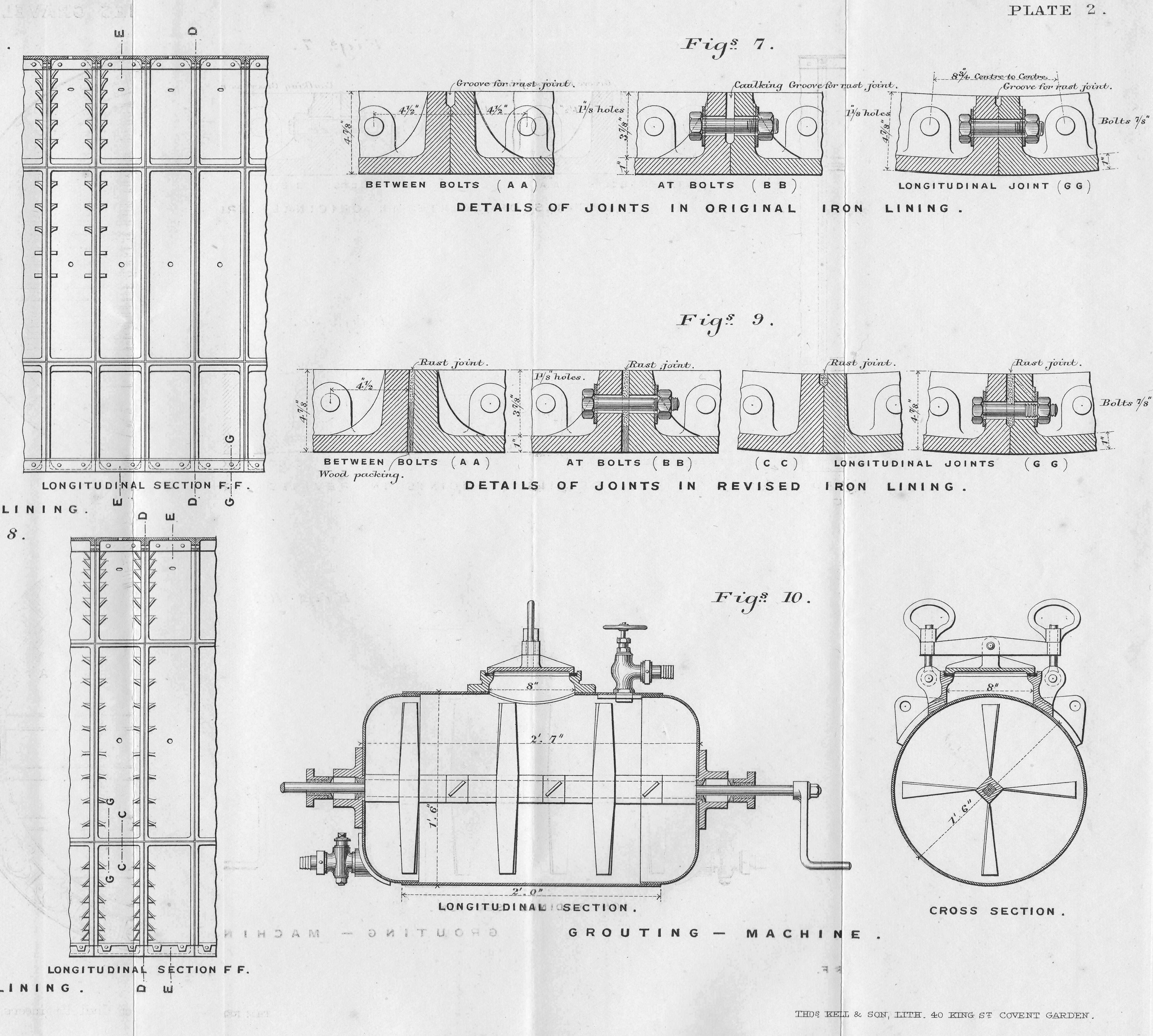
In the late 1970s there was also considerable discussion in Government about how much preparation there should be, and how much the public should be informed about preparing for an attack. Tensions were heightened in 1979 with the Soviet invasion of Afghanistan.

As part of the planning to prepare the general population for an attack, the Protect and Survive booklet was written. This would have been distributed to all households across the country in a period of heightened tensions when a nuclear attack was seen as a possible outcome.

The booklet included advice on how to prepare for an attack and how to survive in the days after an attack.

The front cover of the booklet:

secret nuclear bunker

The front cover is from the Woodrow Wilson International Centre for Scholars and the full booklet is available as a PDF download at the URL in the following citation for the source:

Document-110193,   Author = Great Britain. Central Office of Information and Great Britain. Home Office,  Title  = Protect and Survive, URL  =  http://digitalarchive.wilsoncenter.org/document/110193

Institution = Woodrow Wilson International Center for Scholars publisher   = History and Public Policy Program Digital Archive

A film version of the booklet was also produced for broadcast on TV during the possible lead up to an attack. There is a copy on YouTube here.

The early 1980s also produced some landmark TV and films covering the impact of nuclear war. In September 1984, the BBC produced film Threads was shown on BBC2. A genuinely frightening portrayal of the impact of nuclear war on the city of Sheffield. A sample of the film can be found on YouTube here. I remember it as one of the most frightening programmes I have ever watched then or since on television.
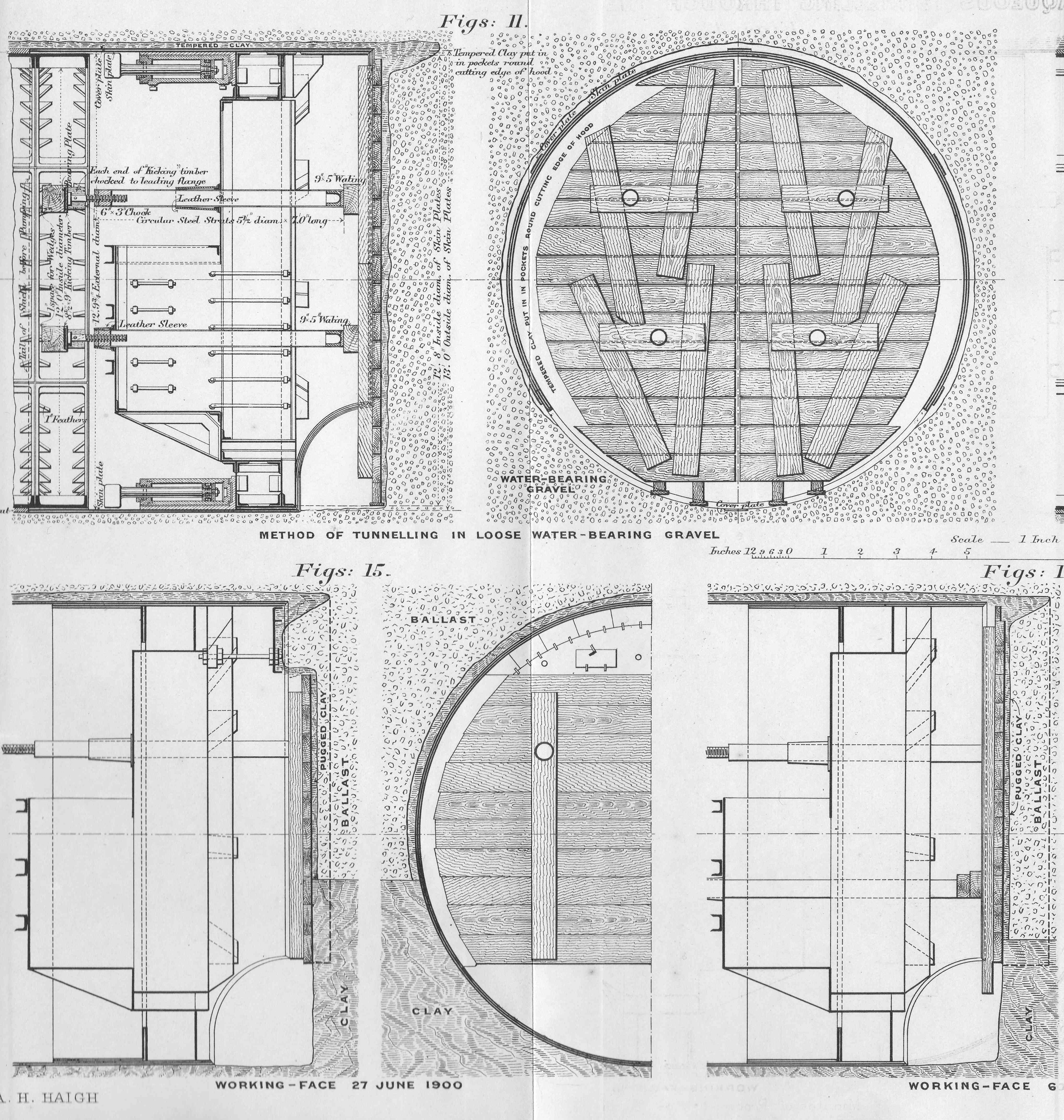
Another example was the 1986 animated film of Raymond Briggs graphic novel, When the Wind Blows.

My just out of school, apprentice excitement at going to such a place as the secret nuclear bunker was most certainly taken back down to earth with the reality of what such a war would mean as depicted in the films mentioned above, as well as so many other books, films, and programmes of the time.
Continuing around the bunker, there is a re-creation of what the room may have looked like where plots would have been drawn on large maps showing where bomb blasts had taken place.
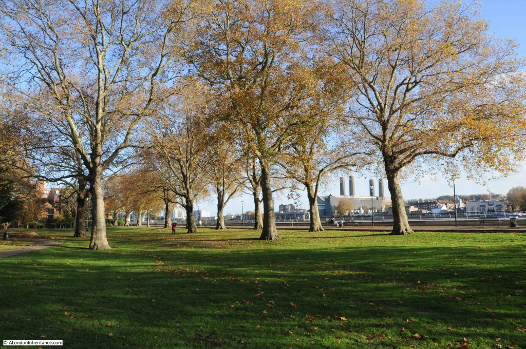
secret nuclear bunker

The position of the Kelvedon Hatch secret nuclear bunker as the regional headquarters for the Greater London area is shown in the following photo:

Continuing further down in the bunker and the air filtration plant. This would have taken in air from the outside and filtered to remove dust and radioactive particles.

secret nuclear bunker

The machine room where equipment maintained the air conditioning of the bunker.

secret nuclear bunker

There are a couple of rooms within the bunker where senior Government officials would have had their own room. One of which was available for the Prime Minister should they have been able to get out of London and into Essex in time.
secret nuclear bunker

The main operations room where representatives of Government departments, the armed forces, transport, energy etc. would have been represented.
secret nuclear bunker

Apparently some of the few items not removed by the Government when they vacated the bunker are the signs around the operations room indicating the working space for each of the Government departments.

secret nuclear bunker

The bunker also contained facilities to accommodate the staff who would have been based here during an attack.

secret nuclear bunker

Up to 600 people would have been based in the bunker in the event of a nuclear war. Whether they would have had any contact with the outside world during their time underground is questionable, and one can only imagine the scene that would have met them when they emerged onto the surface after weeks in the bunker.

It was interesting to return after 40 years. The world is now a very different place, but having places such as the Kelvedon Hatch Secret Nuclear Bunker available to visit are essential to provide a reminder of the real horrors of nuclear war.

Full details are on the web site of the bunker. Thanks to the owners of the bunker for letting me use my photos of the interior.

alondoninheritance.com